Lock-Up Control Solenoid Valves
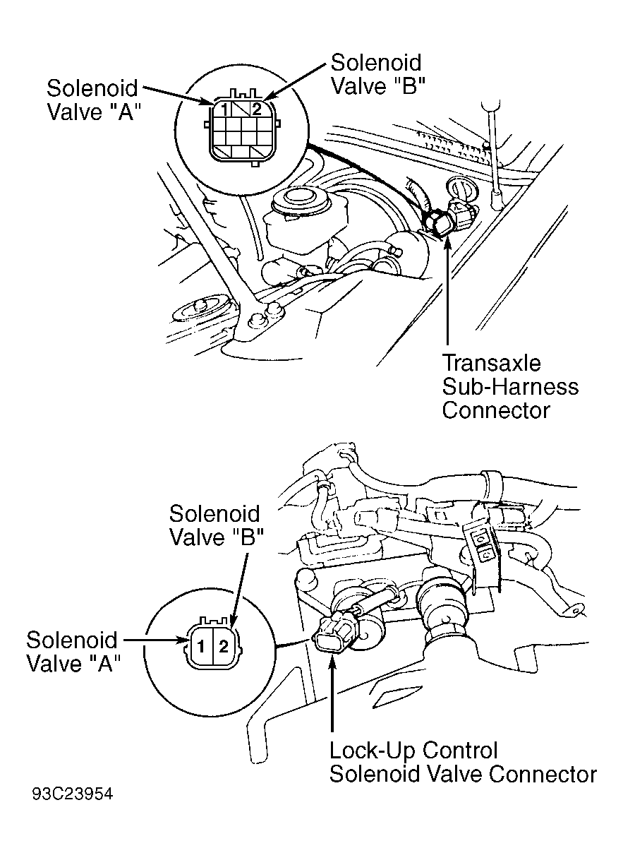
- Lock-up control solenoid valves are located on top of transaxle. See Figure
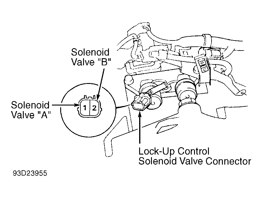
-Figure
. Disconnect transaxle sub-harness connector. See Fig 1
and Fig 2
.
- Using an ohmmeter, measure resistance between terminal No. 1 (Yellow wire ) solenoid valve "A" or terminal No. 2 (Gray wire) solenoid valve "B" and body ground.
- Resistance should be 12-24 ohms. If resistance is not within specification, disconnect lock-up control solenoid valve connector from transaxle sub-harness at the solenoid valves. Note terminal identification on lock-up control solenoid valve connector. See Fig 1
and Fig 2
.
- Using ohmmeter, measure resistance between terminal No. 1 (solenoid valve "A") or terminal No. 2 (solenoid valve "B") of lock-up control solenoid valve connector and body ground.
- Resistance should be 12-24 ohms. If resistance is okay, replace transaxle sub-harness. Replace lock-up control solenoid valve assembly if resistance of either solenoid valve is not within specification.
- To check lock-up control solenoid valve operation, ensure lock-up control solenoid valve body is grounded. Connect battery voltage to terminal No. 1 (solenoid valve "A") or terminal No. 2 (solenoid valve "B") of lock-up control solenoid valve connector.
- Clicking sound should be heard, indicating solenoid valve operation. Replace lock-up control solenoid valve assembly if either solenoid valve fails to operate.
 Courtesy of AMERICAN HONDA MOTOR CO., INC.
 Courtesy of AMERICAN HONDA MOTOR CO., INC.