Shift Control Solenoid Valves
- Shift control solenoid valves are located on lower valve body assembly. See Figure
-Figure
. Shift control solenoid valve "A" has a Blue wire and solenoid valve "B" has a Light Green wire.
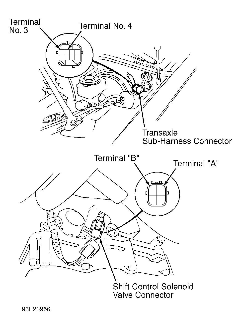
- Disconnect transaxle sub-harness connector. See Fig 1
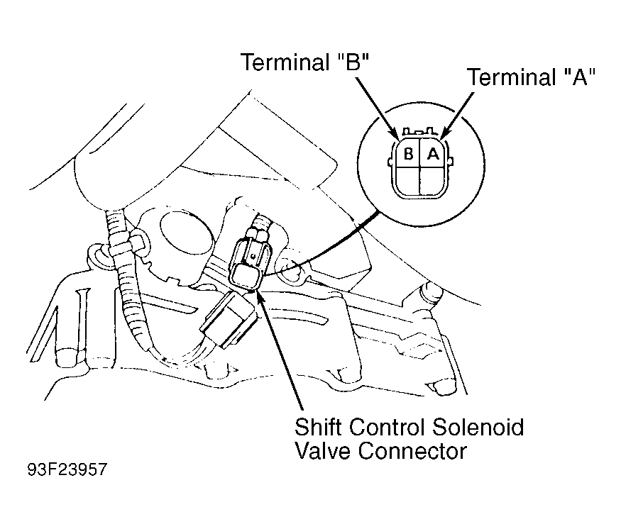
and Fig 2
. Using ohmmeter, measure resistance between terminal No. 3 (Light Green wire) or terminal No. 4 (Blue wire) and body ground.
- Resistance should be 12-24 ohms. If resistance is not within specification, disconnect shift control solenoid valve connector from transaxle sub-harness at the transaxle. Note terminal identification on shift control solenoid valve connector.
- Using ohmmeter, measure resistance between terminal "A" (Blue wire) and body ground. Measure resistance between terminal "B" (Light Green wire) and body ground.
- Resistance should be 12-24 ohms. If resistance is okay, replace transaxle sub-harness. Replace shift control solenoid valve assembly if resistance of either solenoid valve is not within specification.
- To check shift control solenoid valve operation, ensure shift control solenoid valve body is grounded. Apply battery voltage to terminal "A" (Blue wire) and then terminal "B" (Light Green wire) of shift control solenoid valve connector.
- Clicking sound should be heard, indicating solenoid valve operation. Replace shift control solenoid valve assembly if either solenoid valve fails to operate.
 Courtesy of AMERICAN HONDA MOTOR CO., INC.
 Courtesy of AMERICAN HONDA MOTOR CO., INC.