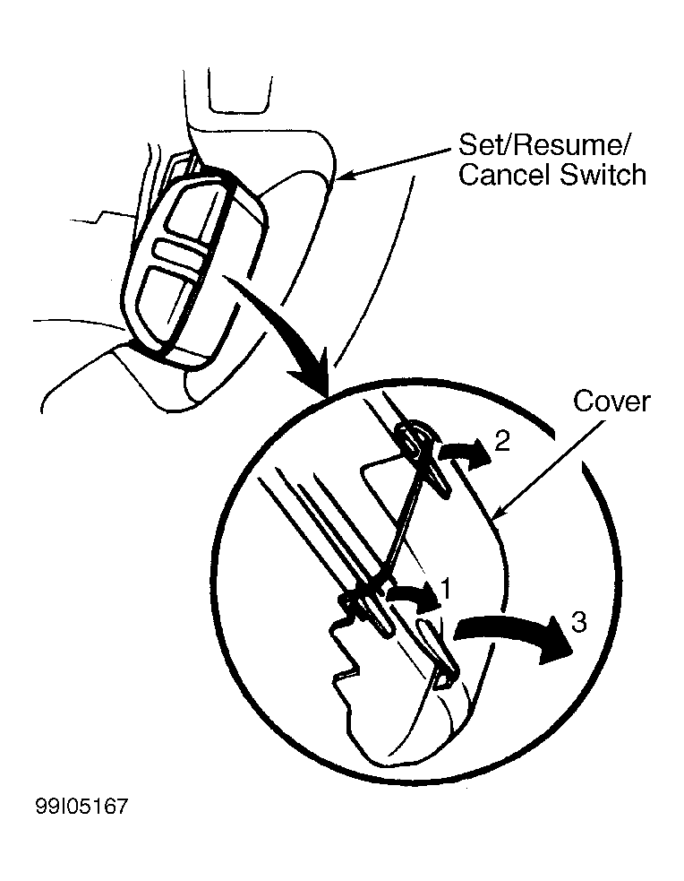
Set/Resume/Cancel Switch: 3.2TL
- Disable air bag system. See appropriate AIR BAG RESTRAINT SYSTEMS article. Remove steering column covers. Disconnect combination switch 4-pin connector. Using an ohmmeter check switch continuity between specified terminals. With SET button depressed (on), continuity should exist between SET/RESUME/CANCEL switch terminals No. 2 and No. 4. See Figure
. With RESUME button pressed (on), continuity should exist between terminals No. 2 and No. 3. With CANCEL button depressed (on), continuity should exist between terminals No. 2 and No. 4, and between terminals No. 2 and No. 3. If continuity exists as specified, go to next step. If continuity does not exist as specified, go to step.
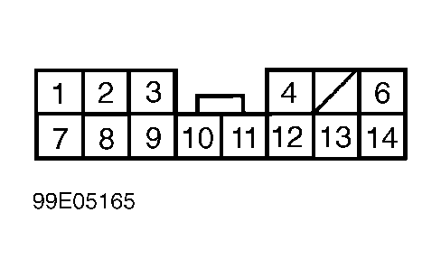
- Remove instrument panel lower cover and knee bolster. Disconnect combination switch Gray 14-pin harness connector between combination switch and main wiring harness located under left side of instrument panel. Using an ohmmeter check harness continuity between specified terminals. Continuity should exists between SET/RESUME/CANCEL switch 4-pin connector terminal No. 3 and combination switch 14-pin harness connector terminal No. 8 and between SET/RESUME/CANCEL switch 4-pin connector terminal No. 4 and combination switch 14-pin connector terminal No. 7. See Fig 1
. If continuity exists, go to next step. If continuity does not exist, replace combination switch wiring harness.
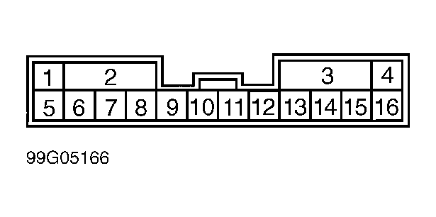
- Disconnect 16-pin connector between combination switch and right engine compartment wire harness. Using an ohmmeter check harness continuity between specified terminals. Continuity should exists between SET/RESUME/CANCEL switch 4-pin harness connector terminal No. 2 and combination switch 16-pin harness connector terminal No. 9. See Fig 2
. If continuity exists, go to next step. If continuity does not exist, replace combination switch wiring harness.
- Remove SET/RESUME/CANCEL switch cover by prying between cover and switch in sequence. See Fig 3
. Remove 2 screws and remove SET/RESUME/CANCEL switch. Using an ohmmeter check switch continuity. With SET button in ON position, continuity should exist between switch terminals No. 1 and No. 3. With RESUME button in ON position, continuity should exist between switch terminals No. 1 and No. 2. With CANCEL button in ON position, continuity should exist between switch terminals No. 1 and No. 2, and between No. 1 and No. 3. Replace switch if continuity is not as specified. If continuity is as specified, replace clockspring. See appropriate AIR BAG RESTRAINT SYSTEMS article.
 Courtesy of AMERICAN HONDA MOTOR CO. INC.
 Courtesy of AMERICAN HONDA MOTOR CO. INC.
 Courtesy of AMERICAN HONDA MOTOR CO. INC.