Cruise Control Communication Circuit
- Start engine. Turn on cruise control main switch. Drive vehicle over 25 MPH and operate cruise control. If cruise control operates, go to next step. If cruise control does not operate, check cruise control unit or actuator. See CRUISE CONTROL UNIT INPUT TEST
under SYSTEM TESTS.
- Turn ignition off. Disconnect PCM 32-pin connector "A" and cruise control unit 14-pin connector. See Fig 1
-Fig 2
. Using DVOM, check for continuity between ground and PCM 32-pin connector "A" terminal No. 5 (Blue/Green wire). If continuity exists, repair short to ground in Blue/Green wire. If continuity does not exist, go to next step.
- Reconnect PCM 32-pin connector "A" and cruise control unit 14-pin connector. Using DVOM to backprobe, measure voltage between ground and cruise control unit connector terminal No. 8. See Fig 2
. Drive vehicle at more than 25 MPH with cruise control set. Voltage should be about one volt. If voltage is as specified, go to next step. If voltage is not as specified, replace cruise control unit.
- Using DVOM to backprobe, measure voltage between ground and PCM 32-pin connector "A" terminal No. 5. See Fig 1
. Drive vehicle at speeds more than 25 MPH with cruise control set and check voltage. Voltage should be about one volt. If voltage is as specified, check connectors for loose, damaged or corroded terminals. If problem exists, repair connector. If problem does not exist, replace PCM and retest system. If voltage is not as specified, repair open or short in Blue/Green wire between PCM connector "A" and cruise control unit.
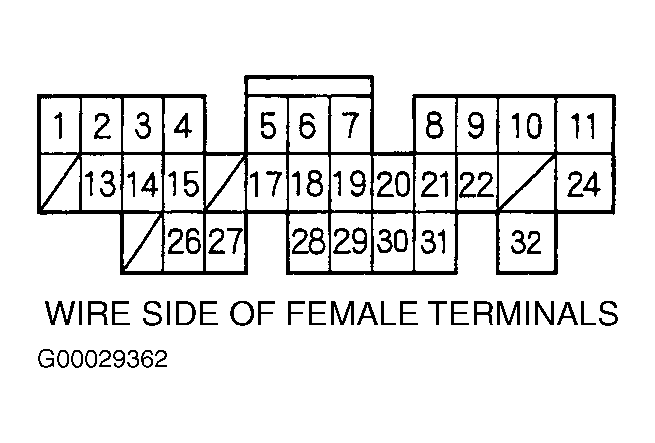 Courtesy of AMERICAN HONDA MOTOR CO., INC.
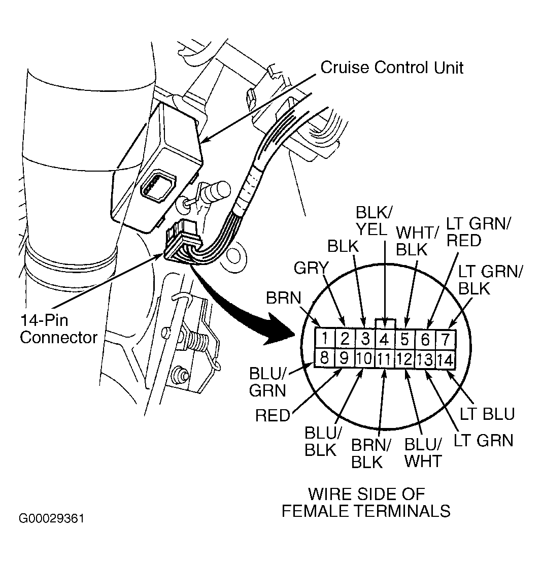 Courtesy of AMERICAN HONDA MOTOR CO., INC.