2005-2006 Models
- If the MIL has been reported on, check for a DTC, and repair the system as indicated by DTC.
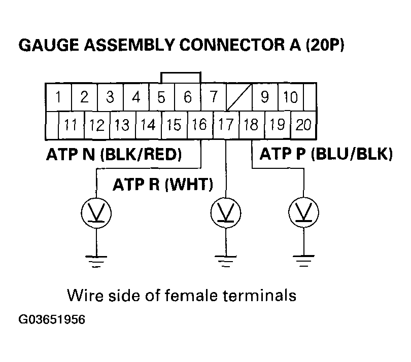
- If the MIL does not come on, and A/T gear position indicator P, R, or N does not come on, remove the gauge assembly from the dashboard, then disconnect the gauge assembly connector A (20P) and B (16P).
- Inspect the connectors and connector terminals to be sure they are making good contact.
- If the terminals are bent, loose, or corroded, repair them as necessary, and recheck the system.
- Turn the ignition switch ON (II).
- Shift to the P position, and check the voltage between gauge assembly terminal A18 (BLU/BLK) and ground. There should be 0 V in the P position and battery voltage in any other shift lever position. If the test results are different, check for faulty transmission range switch or an open in the wire.
 Courtesy of AMERICAN HONDA MOTOR CO., INC.
- Shift to the R position, and check the voltage between gauge assembly terminal A17 (WHT) and ground. There should be 0 V in the R position and battery voltage in any other shift lever position. If the test results are different, check for faulty transmission range switch or an open in the wire.
- Shift to the N position, and check the voltage between gauge assembly terminal A16 (BLK/RED) and ground. There should be 0 V in the N position and battery voltage in any other shift lever position. If the test results are different, check for faulty transmission range switch or an open in the wire.
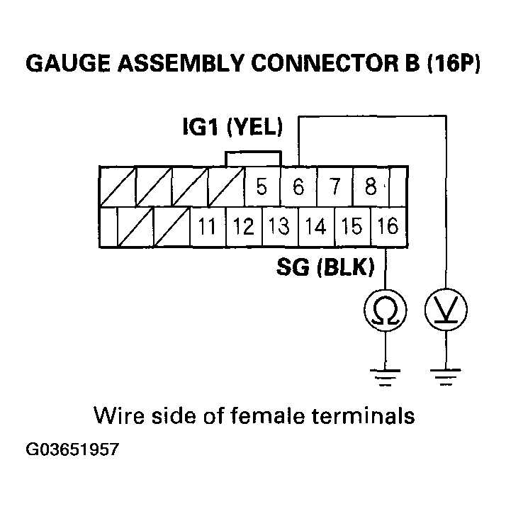
- Check the voltage between gauge assembly terminal B6 (YEL) and ground. There should be battery voltage. If the test result is different, check for a blown No. 10 (7.5 A) fuse in the underdash fuse/relay box or an open in the wire.
 Courtesy of AMERICAN HONDA MOTOR CO., INC.
- Turn the ignition switch OFF, and check for continuity between gauge assembly terminal B16 and ground. There should be continuity under all conditions. If the test result is different, check for a poor ground (G401) or open in the wire.
- If all input tests prove OK, but the indicator is faulty, replace the printed circuit board.