With the HDS
- Turn the ignition switch to LOCK (0).
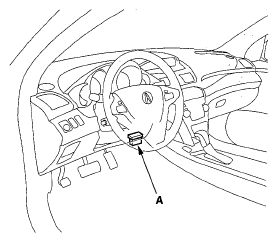
- Connect the HDS to the data link connector (DLC) (A) located under the driver's side of the dashboard.
 Courtesy of AMERICAN HONDA MOTOR CO., INC.
- Turn the ignition switch ON (II).
- Make sure the HDS communicates with the PCM. If it doesn't, go to the DLC circuit troubleshooting (see
DLC CIRCUIT TROUBLESHOOTING
).
- Turn the ignition switch LOCK (0).
- Remove the fuel fill cap to relieve the pressure in the fuel tank.
- Turn the ignition switch to ON (II).
- From the INSPECTION MENU of the HDS, select Fuel Pump OFF, then start the engine, and let it idle until it stalls.
NOTE:
- Do not allow the engine to idle above 1,000 rpm or the PCM will continue to operate the fuel pump.
- A DTC or a Temporary DTC may be set during this procedure. Check for DTCs, and clear them as needed (see
CRANK (CKP) PATTERN CLEAR/CRANK (CKP) PATTERN LEARN
).
- Turn the ignition switch to LOCK (0).
- Do the battery terminal disconnection procedure (See
DISCONNECTION
.
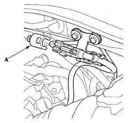
- Remove the quick-connect fitting cover (A).
 Courtesy of AMERICAN HONDA MOTOR CO., INC.
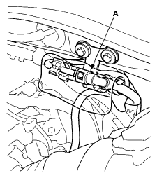
- Check the fuel quick-connect fitting for dirt, and clean it if needed.
- Place a rag or shop towel over the quick-connect fitting (A).
 Courtesy of AMERICAN HONDA MOTOR CO., INC.
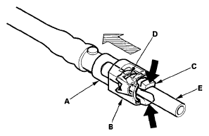
- Disconnect the quick-connect fitting (A): Hold the connector (B) with one hand, and squeeze the retainer tabs (C) with the other hand to release them from the locking tabs (D). Pull the connector off.
NOTE:
- Be careful not to damage the line (E) or other parts.
- Do not use tools.
- If the connector does not move, keep the retainer tabs pressed down, and alternately pull and push the connector until it comes off easily.
- Do not remove the retainer from the line; once removed, the retainer must be replaced with a new one.
 Courtesy of AMERICAN HONDA MOTOR CO., INC.
- After disconnecting the quick-connect fitting, check it for dirt or damage (see step 4
).
- Do the battery terminal reconnection procedure (see
RECONNECTION
).