Audio Remote Switch Test
- Remove the driver's airbag assembly (see
DRIVER'S AIRBAG REPLACEMENT
).
- Remove the 20P connector from the cable reel.
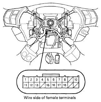 Courtesy of AMERICAN HONDA MOTOR CO., INC.
- Measure the resistance between terminals No. 7 and No. 8 in each switch position according to the table.
RESISTANCE CHART
| Position |
Resistance |
| No button pressed |
About 10 kΩ |
| MODE |
About 3.7 kΩ |
| CH (+) |
About 1.7 kΩ |
| CH (-) |
About 775 Ω |
| ↑ (VOL. UP) |
About 357 Ω |
| ↓ (VOL. DOWN) |
About 100 Ω |
- If the resistance is not as specified, replace the remote switch.
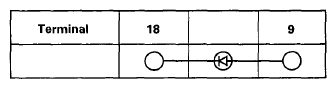
- Use a diode tester between the terminals in each switch position according to the table.
 Courtesy of AMERICAN HONDA MOTOR CO., INC.
- If the diode test is not as specified, replace the switch.