VSA Modulator-Control Unit Connector for Inputs and Outputs (2013-15)
VSA Modulator-Control Unit Inputs and Outputs for 38P Connector (Connector Disconnected)
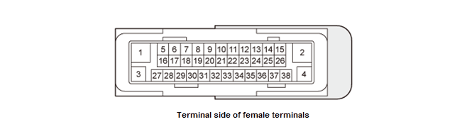 Courtesy of HONDA, U.S.A., INC. Courtesy of HONDA, U.S.A., INC.
|
| Terminal number |
Wire color |
Terminal sign |
Description |
Signal |
| 1 |
BLK |
GND |
Ground for the pump motor |
Continuity to ground |
| 2 |
RED |
+B ABS/VSA MTR |
Power source for the motor relay |
Battery voltage (about 12 V) at all times |
| 3 |
BLK |
GND |
Ground for the VSA modulator-control unit |
Continuity to ground |
| 4 |
YEL |
+B ABS/VSA FSR |
Power source for the fail-safe relay |
Battery voltage (about 12 V) at all times |
| 5 |
RED |
VAC2 |
Detects brake booster pressure sensor B signal |
--- |
| 6 |
Not used |
Not used |
--- |
| 7 |
YEL |
SGND2 |
Ground for brake booster pressure sensor B |
| 8 |
Not used |
Not used |
--- |
| 9 |
GRY |
FR L ABS SNSR- |
Detects left-front wheel speed sensor signal |
| 10 |
Not used |
Not used |
--- |
| 11 |
LT BLU |
K LINE |
Communication with HDS |
Pulse voltage (digital signal) |
| Terminal number |
Wire color |
Terminal sign |
Description |
Signal |
| 12 |
BLU |
SVCC2 |
Power source for brake booster pressure sensor B |
--- |
| 13 |
PNK |
FR R ABS SNSR- |
Detects right-front wheel speed sensor signal |
| 14 |
Not used |
Not used |
--- |
| 15 |
Not used |
Not used |
| 16 |
Not used |
Not used |
| 17 |
Not used |
Not used |
| 18 |
Not used |
Not used |
| 19 |
PUR |
SGND1 |
Ground for brake booster pressure sensor A |
| 20 |
Not used |
Not used |
--- |
| 21 |
ORN |
FR L ABS SNSR+ |
Detects left-front wheel speed sensor signal |
| 22 |
RED |
RR L ABS SNSR- |
Detects left-rear wheel speed sensor signal |
| 23 |
LT GRN |
RR R ABS SNSR+ |
Detects right-rear wheel speed sensor signal |
| 24 |
GRN |
FR R ABS SNSR+ |
Detects right-front wheel speed sensor signal |
| 25 |
Not used |
Not used |
--- |
| 26 |
RED |
F CAN-L |
F-CAN communication circuit |
| 27 |
GRN |
VAC1 |
Detects brake booster pressure sensor A signal |
| 28 |
Not used |
Not used |
--- |
| 29 |
Not used |
Not used |
| 30 |
PNK |
SVCC1 |
Power source for brake booster pressure sensor A |
| 31 |
Not used |
Not used |
--- |
| 32 |
Not used |
Not used |
| 33 |
YEL |
RR L ABS SNSR+ |
Detects left-rear wheel speed sensor signal |
| 34 |
Not used |
Not used |
--- |
| 35 |
WHT |
RR R ABS SNSR- |
Detects right-rear wheel speed sensor signal |
| 36 |
GRN |
IG1 VSA/ABS |
Power source for activating the system |
With vehicle in ON mode: battery voltage (about 12 V) |
| 37 |
Not used |
Not used |
--- |
--- |
| 38 |
WHT |
F CAN-H |
F-CAN communication circuit |