Track Control Arm, Guide Link And Level Control System Sensor Overview
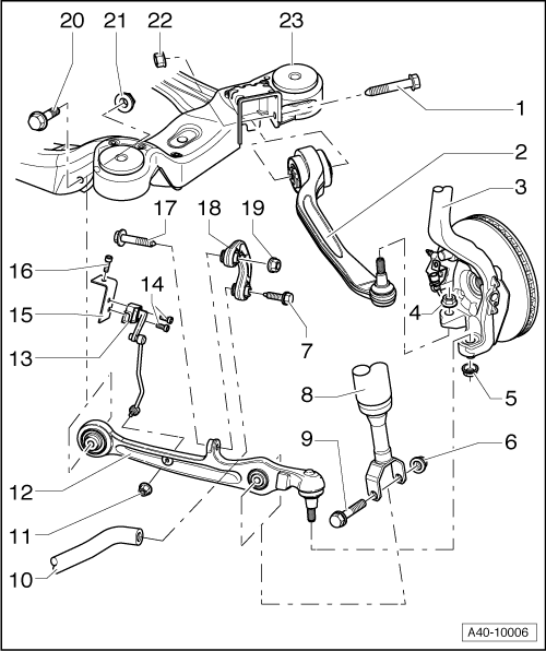 Courtesy of AUDI OF AMERICA, LLC
- Bolt
- 70 Nm + 180° turn
- Always replace if removed.
- Guide Link
- Wheel Bearing Housing
- Nut
- 110 Nm
- Self-locking
- Always replace if removed.
- After loosening threaded connection of guide control arm to wheel bearing housing, adhesive residue must be removed on threads of linkage stub.
- Nut
- 110 Nm
- Self-locking
- Always replace if removed.
- After loosening threaded connection of track control arm to wheel bearing housing, adhesive residue must be removed on thread of linkage stub.
- Nut
- Always replace if removed.
- Bolt
- 40 Nm + 90° turn
- Always replace if removed.
- Shock Absorbers
- Bolt
- 90 Nm + 90° turn
- Always replace if removed.
- Stabilizer Bar
- Nut
- 8 Nm
- Self-locking
- Always replace if removed.
- Control Arm
- Left Front Level Control System Sensor -G78- or Right Front Level Control System Sensor -G289-
- Bolt
- Securing Clip
- Bolt
- Bolt
- 40 Nm + 90° turn
- Always replace if removed.
- Coupling Rod
- Nut
- Always replace if removed.
- Bolt
- 70 Nm + 180° turn
- Always replace if removed.
- Nut
- Always replace if removed.
- Nut
- Always replace if removed.
- Subframe