Test Group TBM2.8VJGKEK
- Misfire Monitoring General Description
- Measure Principle -
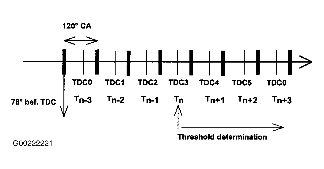
Method of engine misfire detection is based on monitoring crankshaft acceleration. Engine roughness is derived from differences from segment periods (120 degree crank angle) durations which are corrected and compared to a load and engine-speed dependent thresholds. Different statistical methods are used to distinguish between normal changes of segment duration and changes due to misfire. See Fig 1. Segment periods are measured through an angular range of 120 degree crank angle. The segment starts 78 degrees before TDC. Beginning and end of the segments are located at the same angle. Duration of crankshaft segments is measured continuously.
- Sensor Wheel Adaptation -
To eliminate manufacturing tolerances and off-center installation, adaptation of sensor wheel tolerances is carried out during fuel cut-off. Segment periods are corrected by adaptation values. With progressing adaptation, sensitivity of misfire detection is increased.
- Calculation Of Engine Roughness Threshold Value -
Engine roughness threshold value consists of base value, which is determined by a load/speed dependent map. During warm-up, base value is multiplied by a coolant temperature dependent correction value. Without sufficient sensor wheel adaptation, engine roughness threshold is limited depending on wheel tolerances expected.
- Disablement Of Misfire Detection -
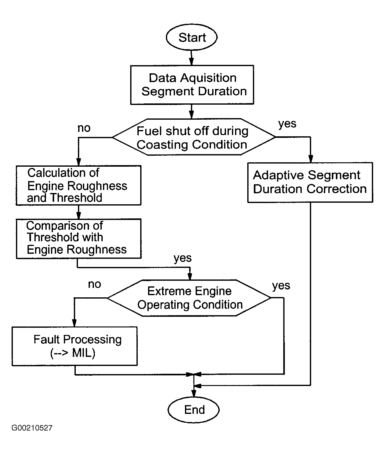
The misfire detection is deactivated during the following extreme operating conditions:
- Engine speed less than 512 RPM.
- Engine load less than minimum load = positive torque line, including disablement area between 3000-6240 RPM.
- Load during 120 degree crank angle is changing rapidly - disablement for .5 second.
- Throttle angle is changing rapidly - disablement for .7 second.
- Retarded ignition timing. Various functions or CAN requests (gearshift signal, torque reduction) cause retarded ignition. This results in jumps of segment periods and crankshaft vibration which cannot be distinguished from misfire disablement: during 12 x 120 degree (4 crankshaft revolutions), if retarded timing ignition exceeds 10.1 degree crank angle.
- During engine start and up to 5 seconds after start.
- When air conditioning is switched on for .5 second.
- During fuel cut-off for one or more cylinders.
- Rough road conditions:
- Wheel speed fluctuation (greater than 6 rev/sec. or less than 42 rev/sec.).
- Dependent on vehicle speed (greater than 1.8 MPH or less than 130 MPH.).
- Disabled for .25-1.0 seconds.
- Misfire Monitoring, Fault Processing -
For fault processing flow chart, see Fig 2.
- Error Window -
Within an interval of 200-1000 crankshaft revolutions, "error windows" to check for similar engine conditions are determined. Upon detection of misfire, window is extended if current operating point is not within the window.
- Engine Operating Point Window -
Engine operating window is updated with each segment without misfire.
- Misfire Detection (Emission Increase) -
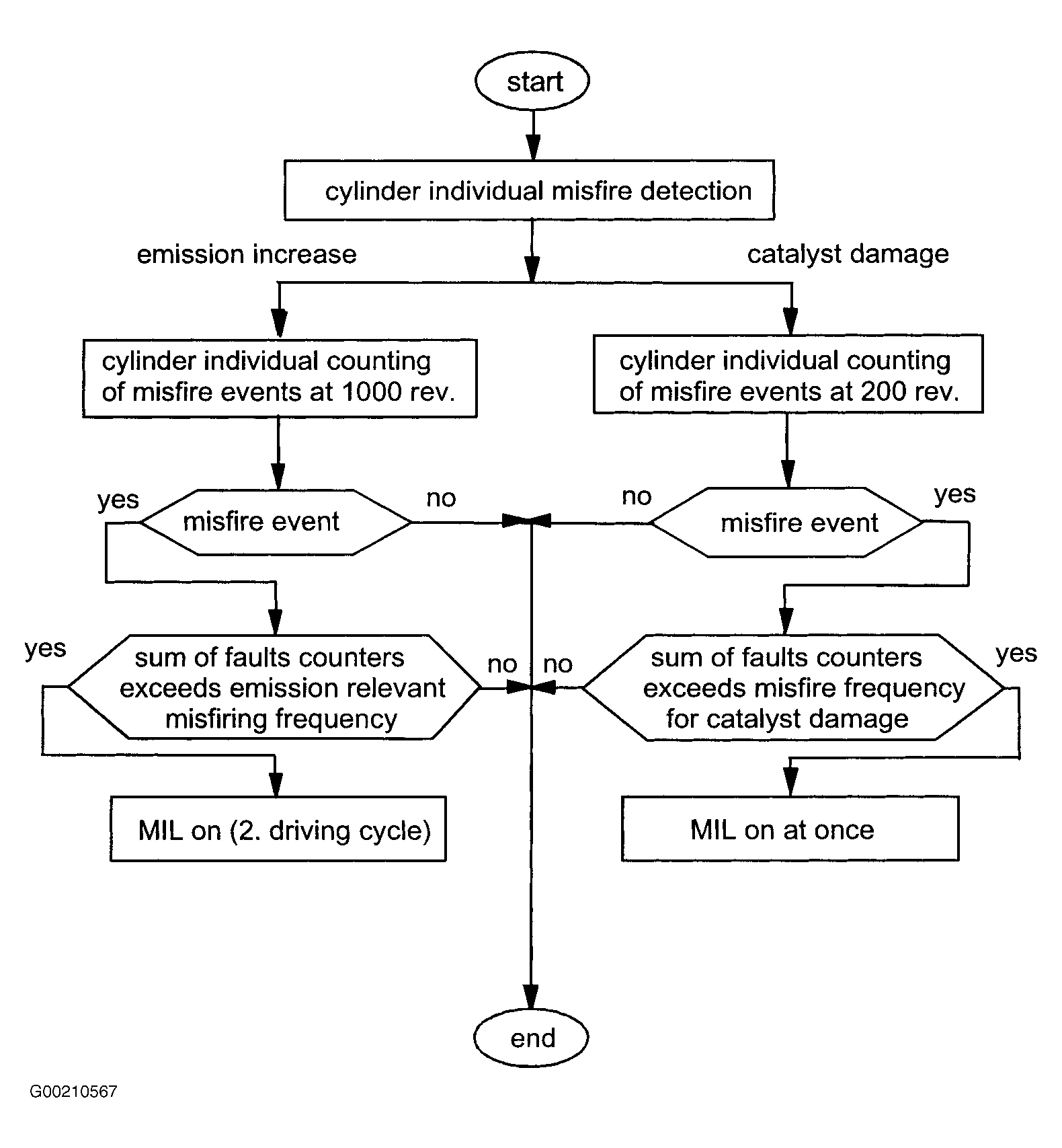
Within an interval of 1000 crankshaft revolutions (3000 segments), detected misfire events are added for each cylinder. If sum of all cylinder misfire incidents exceed a predetermined value, a fault code is stored. If more than one cylinder is misfiring, all misfiring cylinders will be specified and individual fault codes for all misfiring cylinders and for multiple cylinder will be stored. Within an interval of 200 crankshaft revolutions, detected number of misfiring events is weighted and calculated for each cylinder. Weighting factor is determined by a load/speed dependent map. If sum of cylinder misfire incidents exceeds a predetermined value, a fault code is stored and MIL is illuminated immediately. If cylinder selective count exceeds predetermined threshold, following measures take place:
- Lambda closed loop system is switched to open loop.
- Cylinder selective fault code is stored.
- If more than one cylinder is misfiring, fault codes for all individual cylinders will be stored.
- Fuel supply to respective cylinder is cut-off.
All misfire counters are reset after each interval. See Fig 3.
 Courtesy of BMW OF NORTH AMERICA, INC.
 Courtesy of BMW OF NORTH AMERICA, INC.
 Courtesy of BMW OF NORTH AMERICA, INC.