Steering Column
- Install wave washer and jacket mounting plate in place. Work jacket mounting plate into notches in jacket by tipping jacket mounting plate toward bowl hub at 12 o'clock position and under jacket opening. Slide jacket mounting plate into notches in jacket.
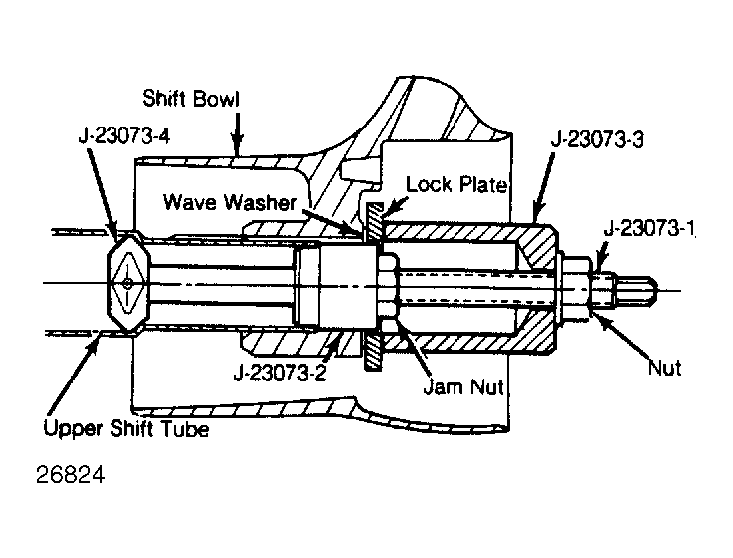
- If previously removed, carefully install shift tube into lower end of jacket. Align key in tube with keyway in bowl. Use Installer (J-23073 or C-4119) to pull shift tube into bowl. DO NOT
tap on end of shift tube.
- Install thrust washer and retaining ring by pulling bowl up to compress wave washer. Slide dimmer switch actuator rod through hole in support. Install support by aligning "U" in support with "U" notch in jacket.
 Courtesy of GENERAL MOTORS CORP.
- Insert 4 screws through support into lock plate. Tighten screws to 60 INCH lbs. (7 N.m). Reinstall lower bearing (if removed) approximately 3/16" (4.8 mm) into tube. Slide ignition actuator rod between bowl and jacket. Install centering spheres and anti-lash spring into upper steering shaft.
- Install lower steering shaft from same side of spheres that spring ends protrude. Make a trial assembly of shaft couplings to ensure that master serration of upper shaft will align with master serration of pot coupling (lower shaft). Position shift bowl in "PARK".
- Hold lock shoes in disengaged position. Install bearing housing over steering shaft until pivot pin holes align with holes in support. Ensure rack has engaged ignition switch actuator rod.
- Install pivot pins. Use hand pressure to prevent broaching of support pivot holes. Tap with a small hammer and drift to complete installation. Place housing in full "UP" position.
- Install guide and peg on support. Install tilt spring and spring retainer. Using a screwdriver, turn retainer clockwise to engage. Install inner bearing race and seat. Install tilt lever opening shield in housing (if removed).
- Remove tilt release lever, install housing cover, and seat screw at 12 o'clock position. Tighten 3 screws to 100 INCH lbs. (11 N.m). Install buzzer/chime switch to spring clip with spring bowed away from switch on side opposite contact.
- Push switch and spring into hole in cover with contacts toward lock cylinder. Install key light (if equipped). Install turn signal switch. Feed wires and connector through cover, bearing housing, and shift bowl.
- Install hazard warning knob. Install canceling cam, cam spring, and shaft lock plate. Using Compressor (J-23653 or C-4156), depress lock plate and install new retaining ring.
- Reinstall tilt release lever and turn signal switch lever. Install upper shift lever and drive in pivot pin. Position shaft lock cover over lock. Snap into position by pressing on outer edges.
- To install ignition lock, turn key to "LOCK" position and remove key. This will cause buzzer operating lever to retract in cylinder. Slide ignition switch to "LOCK" position, second detent from bottom.
- Insert cylinder into housing far enough to contact drive shaft. Press inward and move ignition switch actuator rod up and down to align parts. When parts align, cylinder will move inward and a spring loaded retainer will snap into place locking the cylinder into housing.
- Push ignition switch lightly up column, toward lock housing, to take out lash in actuator rod. Tighten mounting screws to 35 INCH lbs. (4 N.m). Install wire protector over wires on column jacket. Be careful not to pinch any wires. To complete assembly, refer to STEERING COLUMN R & I in this article.
- Install dimmer switch. Firmly seat actuator rod into switch. Depress switch until one 3/32" (2.38 mm) drill bit can be inserted.
- On all models, reposition upper end of push rod in pocket of washer/wiper switch. With light upward pressure on switch to remove lash, install and tighten 2 screws on switch. Remove drill bit(s). The switch should click when lever is lifted.