Removal Procedure
- Install the engine support fixture. Refer to the following procedures:
- Raise and support the vehicle. Refer to Lifting and Jacking the Vehicle
in General Information.
- Remove the front tires and wheels. Refer to Tire and Wheel Removal and Installation
in Tires and Wheels.
- Remove the radiator lower air deflector. Refer to Radiator Air Baffle and Deflector Replacement - Lower
in Engine Cooling.
- Disconnect the fog lamp electrical connectors and position aside.
- Remove the positive battery cable and retainers from the frame and position the cable aside. Refer to Battery Positive Cable Replacement
in Engine Electrical.
- Disconnect the power steering cooler pipe from the frame. Refer to Power Steering Cooler Pipe/Hose Replacement (L26)
in Power Steering System.
- Secure the power steering cooler.
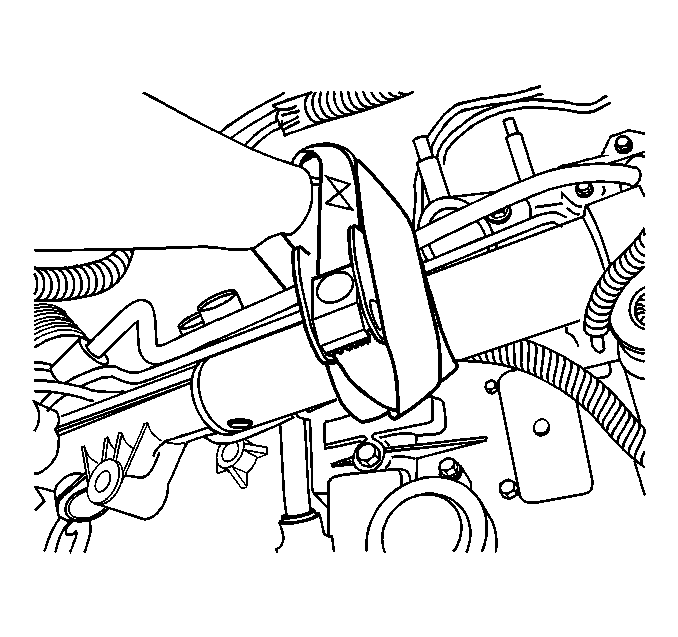
- Remove the stabilizer shaft links and rotate the stabilizer shaft up in order to gain access to the mounting bolts on the power steering gear. Refer to Stabilizer Shaft Link Replacement
in Front Suspension.
- Remove the mounting bolts. Refer to Power Steering Gear Replacement
in Power Steering System.
 Courtesy of GENERAL MOTORS CORP.
- Secure the power steering gear.
- Remove the nuts that secure the engine mount to the frame. Refer to the following procedures:
- Remove the nuts which secure the transaxle mount to the frame. Refer to Automatic Transmission Mount Replacement
in Automatic Transaxle.
 Courtesy of GENERAL MOTORS CORP.
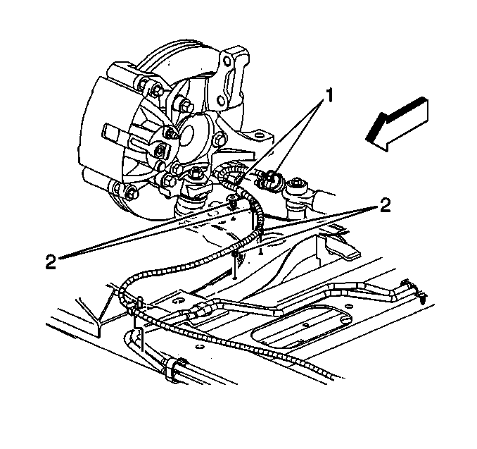
- Disconnect both front wheel speed sensor connectors (1), if equipped.
- Remove both speed harness retainers (2) from the frame and the lower control arms, if equipped.
- Separate both of the lower ball joints from the steering knuckle. Refer to Lower Control Arm Replacement
in Front Suspension.
 Courtesy of GENERAL MOTORS CORP.
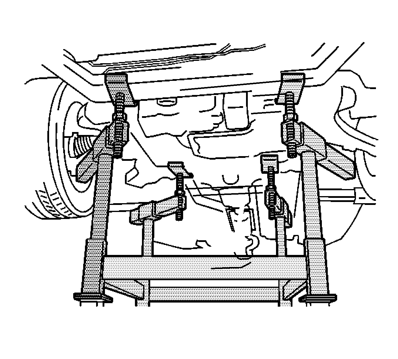
- Lower the vehicle until the frame contacts J 39580
. See Special Tools and Equipment .
 Courtesy of GENERAL MOTORS CORP.
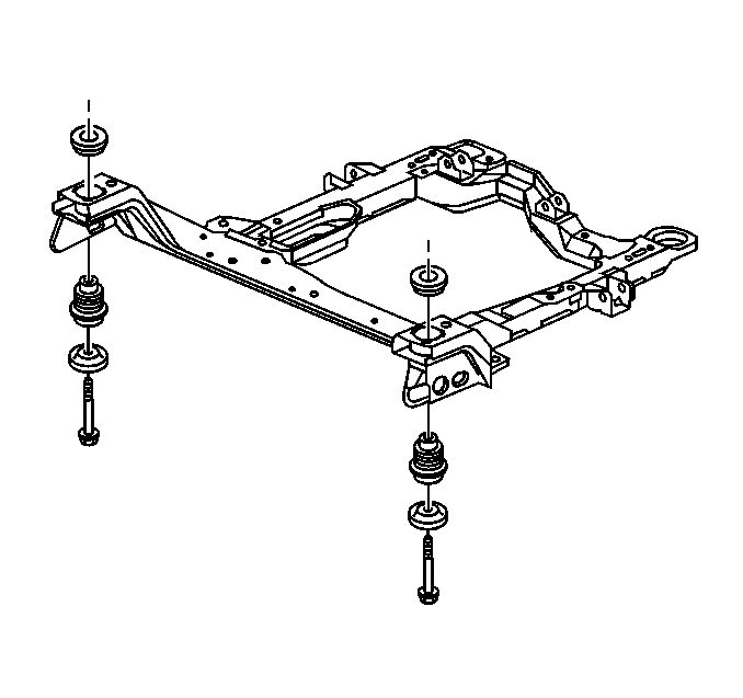
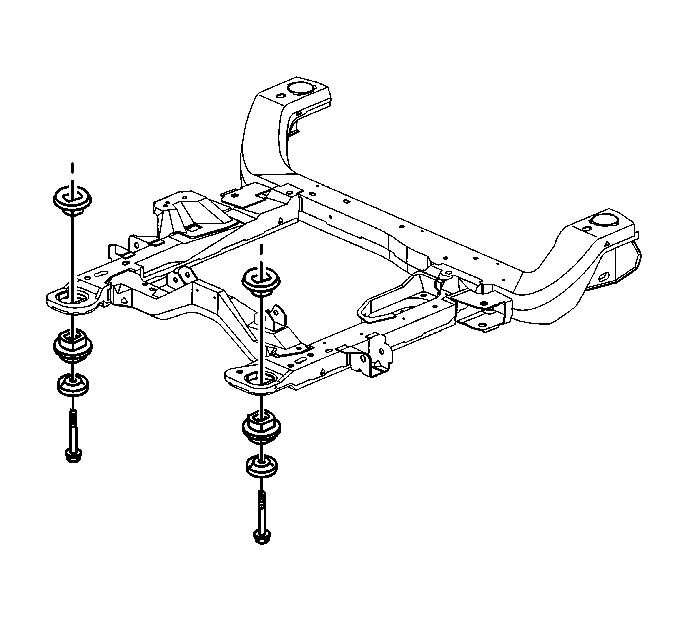
- Remove and DISCARD the bolts which secure the front frame to the body.
 Courtesy of GENERAL MOTORS CORP.
- Remove the bolts which secure the rear frame to the body.
- Raise the vehicle in order to separate the frame from the body.
- If you are replacing the frame, remove the following components: