Test 14: Lumbar Support Inoperative - Without A45
- Perform LUMBAR SUPPORT SYSTEM CHECK - WITHOUT A45
under TROUBLE SHOOTING. Go to next step.
- Disconnect lumbar switch connector. Measure voltage between ground and lumbar switch connector terminal "G" (Orange wire). See Fig 1
. If voltage is 9-16 volts, go to next step. If voltage is not 9-16 volts, go to step 5
.
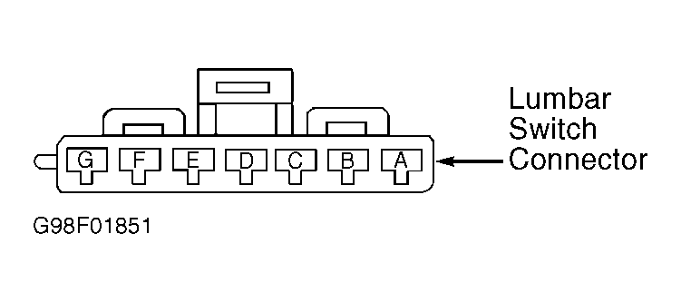 Courtesy of GENERAL MOTORS CORP.
- Measure voltage between lumbar switch connector terminals "G" (Orange wire) and "E" (Black wire). If voltage is 9-16 volts, go to next step. If voltage is not 9-16 volts, go to step 6
.
- Check lumbar switch connector for poor connections. If problem is found, repair as necessary, then go to step 8
. If problem is not found, go to step 7
.
- Repair open in Orange wire between lumbar switch and rear junction block. After repairs, go to step 8
.
- Repair open in Black wire between lumbar switch and ground. After repairs, go to step 8
.
- Replace lumbar switch. See POWER SEAT SWITCHES under REMOVAL & INSTALLATION in POWER SEATS - SEVILLE
article. After repairs, go to next step.
- Operate system to verify repair. If system operates normally, repair is complete. If system does not operate normally, return to step 2
.