Removal Procedure
- Raise and support the vehicle. Refer to Lifting and Jacking the Vehicle
in General Information.
- Remove the tire and wheel. Refer to Tire and Wheel Removal and Installation
in Tires and Wheels.
 Courtesy of GENERAL MOTORS CORP.
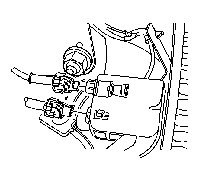
- Disconnect the wheel speed sensor electrical connector.
- Disconnect the brake wear sensor electrical connector.
 Courtesy of GENERAL MOTORS CORP.
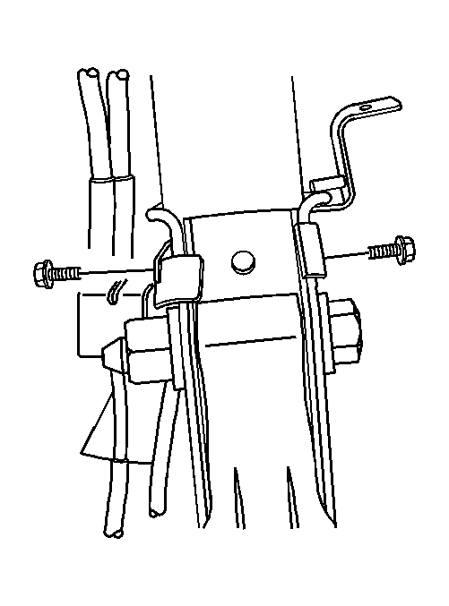
- Remove the wheel speed sensor bracket and retaining bolt from the strut.
- Remove the brake line bracket and retaining bolt from the strut.
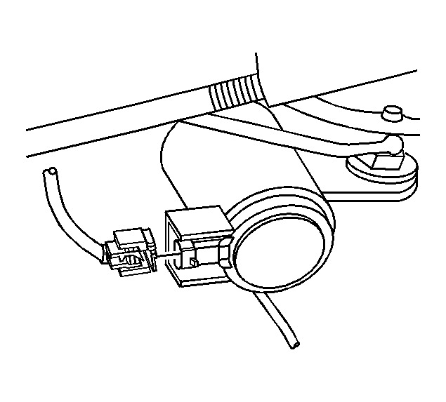
- Disconnect the road sensing suspension electrical connector (if equipped).
 Courtesy of GENERAL MOTORS CORP.
- Disconnect the MAGNERIDE™ electrical connector (if equipped).
 Courtesy of GENERAL MOTORS CORP.
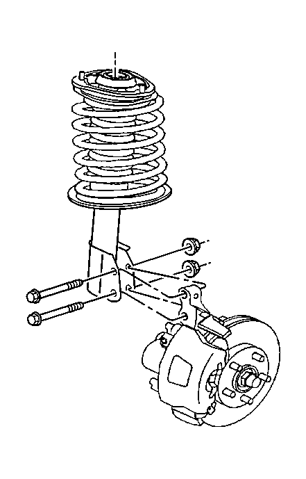
- Remove the strut to steering knuckle mounting bolts and nuts.
- Lower the vehicle.
 Courtesy of GENERAL MOTORS CORP.
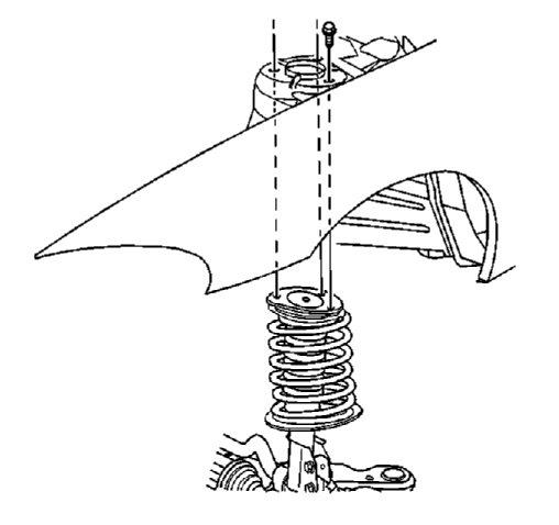
- Remove the upper strut mount retaining bolts.
- Remove the strut from the vehicle.