Removal Procedure
- Remove the steering column from the vehicle. Refer to Steering Column Replacement (Without HP2)
, Steering Column Replacement (HP2)
, Steering Column Replacement (Without HP2 With Electric Tilt Column)
.
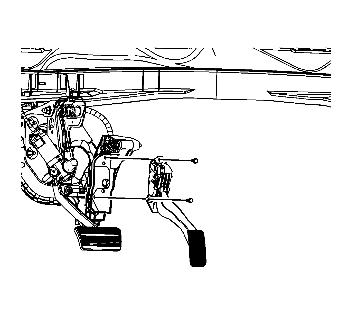
- Disconnect the electrical connectors from the following components:
- Adjustable pedal motor assembly
- Memory sensor connector, if equipped
- Brake pedal position sensor
- Stoplamp switch
 Courtesy of GENERAL MOTORS CORP.
- Remove the accelerator pedal position sensor assembly. Refer to Accelerator Pedal Position Sensor Replacement
.
- Remove the left side floor air outlet duct. Refer to Floor Air Outlet Duct Replacement - Left Side
.
 Courtesy of GENERAL MOTORS CORP.
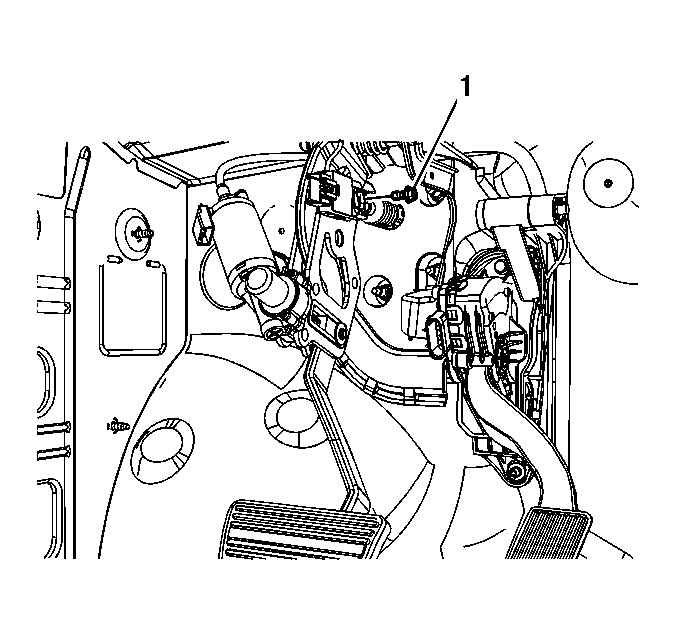
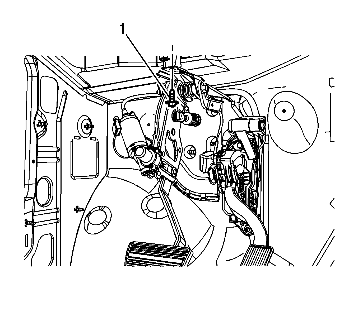
- Remove the brake booster pushrod retainer bolt (1).
 Courtesy of GENERAL MOTORS CORP.
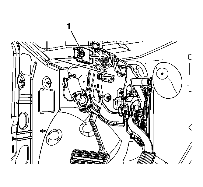
- Remove the brake booster pushrod retainer (1).
 Courtesy of GENERAL MOTORS CORP.
- Remove the stoplamp switch (1).
- Disconnect the brake booster pushrod from the brake pedal pivot.
 Courtesy of GENERAL MOTORS CORP.
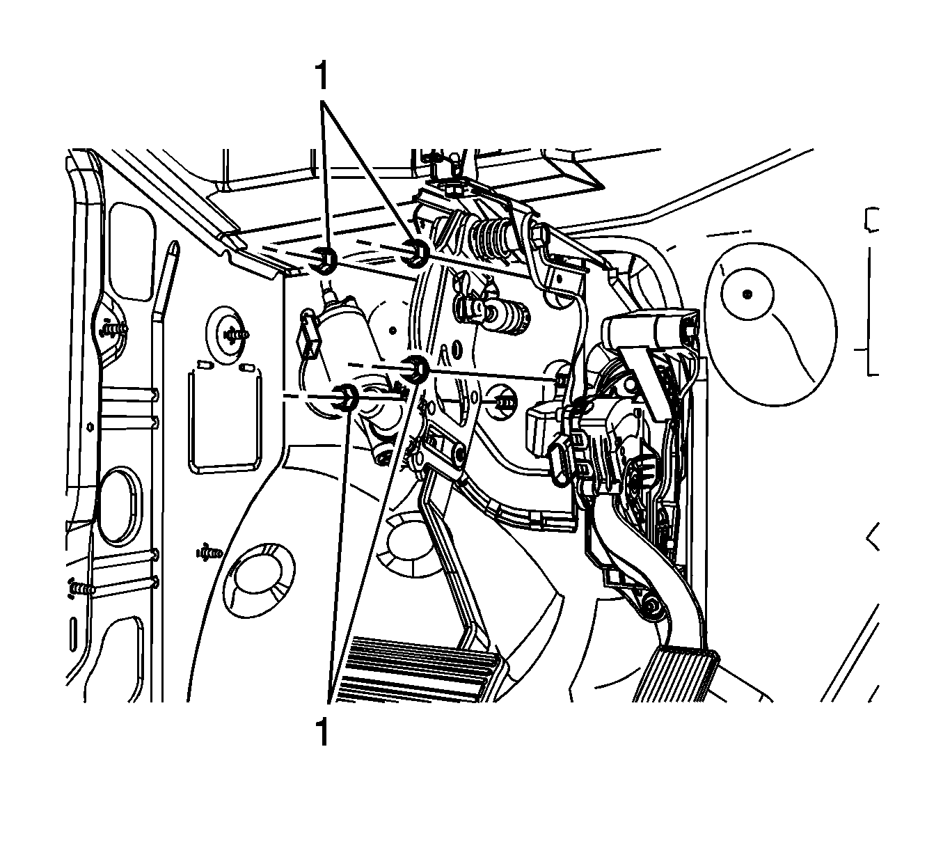
- Remove the adjustable pedal bracket nuts (1).
 Courtesy of GENERAL MOTORS CORP.
- Remove the adjustable pedal bracket bolt (1).
- Position the brake booster forward until the studs are past the adjustable pedal bracket holes and support with heavy mechanics wire or equivalent.
- Disconnect and position aside any wiring harnesses as necessary.
- Remove the adjustable pedal assembly from the vehicle.