Test A: Both Mirrors Inoperative
- Check fuse No. 19 (10-amp) located in fuse block, at right end of instrument panel. If fuse is open, go to next step. If fuse is okay, go to step 3
.
- Repair short to ground in Orange wire between instrument panel fuse block and power mirror switch. See WIRING DIAGRAMS
. Replace fuse. After repair, perform system operation check. See SYSTEM OPERATION CHECK
under TROUBLE SHOOTING.
- Remove power mirror switch. Disconnect power mirror switch 6-pin harness connector C1. Using test light connected to ground, probe power mirror switch harness connector C1 terminal "F" (Orange wire). See Fig 1
. If test light illuminates, go to next step. If test light does not illuminate, go to step 8
.
- Using test light, probe between power mirror switch connector C1 terminals "F" (Orange wire) and "D" (Black wire). See Fig 1
. If test light illuminates, go to next step. If test light does not illuminate, go to step 9
.
- Inspect power mirror switch harness connector C1 for poor connection or loose terminals. If connection is faulty, go to next step. If connection is not faulty, go to step 7
.
- Repair poor connection or loose terminals in power mirror switch harness connector C1. After repair, perform system operation check. See SYSTEM OPERATION CHECK
under TROUBLE SHOOTING.
- Replace power mirror switch. After repair, perform system operation check. See SYSTEM OPERATION CHECK
under TROUBLE SHOOTING.
- Repair open or high resistance in Orange wire between power mirror switch and instrument panel fuse block. See WIRING DIAGRAMS
. After repair, perform system operation check. See SYSTEM OPERATION CHECK
under TROUBLE SHOOTING.
- Measure resistance between ground and power mirror switch harness connector C1 terminal "D" (Black wire). If resistance is 2 ohms or more, go to next step. If resistance is less than 2 ohms, problem may be intermittent, go to step 3
.
- Repair open in Black wire between power mirror switch and ground. Ground point is located at base of right "B" pillar. After repair, perform system operation check. See SYSTEM OPERATION CHECK
under TROUBLE SHOOTING.
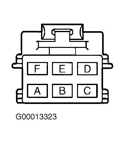 Courtesy of GENERAL MOTORS CORP.