Diagnostic Procedure
- Perform powertrain diagnostic system check. See POWERTRAIN DIAGNOSTIC SYSTEM CHECK under SELF-DIAGNOSTIC SYSTEM. After performing powertrain diagnostic system check, go to next step.
- Using scan tool, check for other DTCs. If any other DTCs are set, diagnose those DTCs first. See DIAGNOSTIC TROUBLE CODE DEFINITIONS . If no other DTCs are set, go to next step.
- Turn ignition on, with engine off. Using scan tool, review FREEZE FRAME data and note parameters. Start engine and operate vehicle as close to conditions recorded in FREEZE FRAME as possible. Select SPECIFIC DTC function. If scan tool displays DTC P0101 FAILED THIS IGNITION, go to next step. If scan tool does not display DTC P0101 FAILED THIS IGNITION, go to DIAGNOSTIC AIDS .
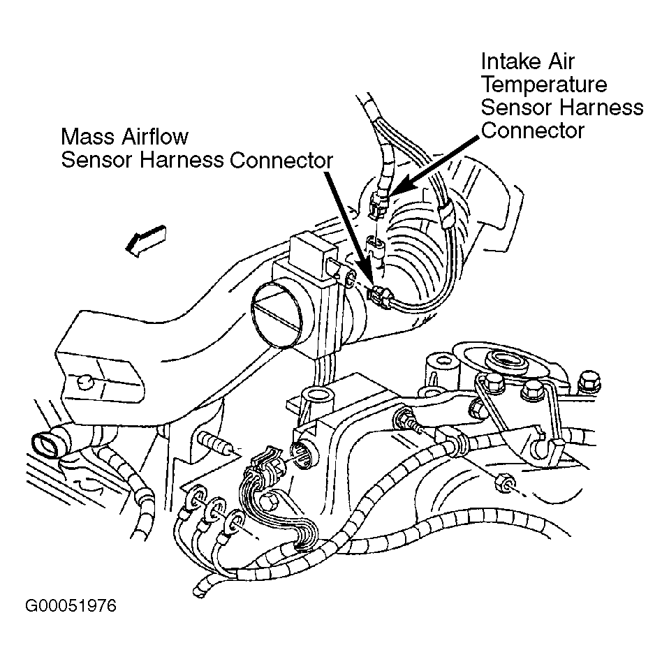
- DO NOT clear DTCs. Disconnect MAF sensor harness connector. See Fig 1. Attempt to start engine. If engine starts and continues to run, go to next step. If engine does not start and continue to run, go to step 6.
- Turn ignition off. Reconnect MAF sensor harness connector. Start engine. Monitor MAP signal on scan tool. Slowly increase engine speed to 3000 RPM. If MAP sensor signal changes as engine speed increases, go to step 7. If MAF sensor signal does not change as engine speed increases, go to next step.
- Diagnose MAP sensor circuit. See ENGINE SENSORS & SWITCHES in appropriate SYSTEM & COMPONENT TESTING article. After repairs, go to step 20.
- Turn ignition on. Ensure throttle is closed. Using scan tool, observe throttle angle parameter. If scan tool indicates 0%, go to next step. If scan tool does not indicate 0%, diagnose using DTC P0121. See DTC P0121: TP SENSOR PERFORMANCE .
- Turn ignition off. Disconnect MAF sensor harness connector. Turn ignition on. Measure voltage between ground and signal circuit (Dark Green/White wire) at MAF sensor harness connector terminal "A". If voltage is about 5 volts, go to next step. If voltage is not about 5 volts, go to step 10.
- Connect test light between ignition feed circuit (Pink wire) at MAF sensor harness connector terminal "C" and ground circuit (Black/White wire) at MAF sensor harness connector terminal "B". If test light illuminates, go to step 13. If test light does not illuminate, go to step 12.
- If voltage is less than 4.5 volts, go to step 14. If voltage is not less than 4.5 volts, go to next step.
- Turn ignition off. Disconnect PCM harness connectors. PCM is located on right side of engine compartment, in front of strut tower. Turn ignition on. Measure voltage between ground and signal circuit (Dark Green/White wire) at MAF sensor harness connector terminal "A". If voltage is near zero volts, go to step 20. If voltage is not near zero volts, go to step 17.
- Connect test light between ground and ignition feed circuit (Pink wire) at MAF sensor harness connector terminal "C". If test light illuminates, go to step 15. If test light does not illuminate, go to step 16.
- Check for poor connection at MAF sensor connector. Repair as necessary. After repairs, go to step 20. If connection is okay, go to step 18.
- Check for high resistance or short to ground in signal circuit (Dark Green/White wire) between MAF sensor harness connector terminal "A" and PCM harness connector C1 terminal No. 69. Check for high resistance in sensor ground circuit (Black/White wire) between MAF sensor harness connector terminal "B" and ground point located near starter. Check for poor connection at PCM. If a problem is found, repair as necessary, then go to step 20. If no problems are found, go to step 19.
- Repair open in MAF sensor ground circuit (Black/White wire) between MAF sensor harness connector terminal "B" and ground point located near starter. After repairs, go to step 20.
- Repair open or excessive resistance in MAF sensor ignition feed circuit (Pink wire). After repairs, go to step 20.
- Repair short to voltage in MAF sensor signal circuit (Dark Green/White wire). After repairs, go to step 20.
- Replace MAF sensor. After repairs, go to step 20.
- Replace PCM. Program replacement PCM using required equipment. See PROGRAMMING . After repairs, go to next step.
- Using scan tool, review and record FAILURE RECORDS data. Clear DTCs. Start engine and operate vehicle as close to conditions recorded in FAILURE RECORDS as possible. If DTC resets, go to step 2. If DTC does not reset, system is okay.
 Courtesy of GENERAL MOTORS CORP.