Engine Does Not Crank, Starter Solenoid Does Not Click
- Connect scan tool to Data Link Connector (DLC). See COMPONENT LOCATIONS
. Turn ignition on. Select PCM DATA LIST. Observe COMMANDED STARTER parameter while turning ignition switch to START position. If scan tool displays ENABLED, go to next step. If scan tool does not display ENABLED, go to step 10
.
- Locate crank relay. Listen for a "click" from crank relay while turning ignition switch to START position. If a "click" sound is heard from crank relay while turning ignition switch to START position, go to step 7
. If no "click" sound is heard from crank relay while turning ignition switch to START position, go to next step.
- Turn ignition off. Disconnect crank relay. Turn ignition on. Connect test light between ground and crank relay coil feed circuit cavity No. 85 (Orange/Black wire). See WIRING DIAGRAMS
. If test light illuminates, go to next step. If test light does not illuminate, go to step 5
.
- Connect test light between crank relay coil feed circuit cavity No. 85 (Orange/Black wire) and crank relay control circuit cavity No. 86 (Yellow/Black wire). Turn ignition switch to START position. If test light illuminates, go to step 15
. If test light does not illuminate, go to step 12
.
- Turn ignition off. Locate and disconnect Park/Neutral Position (PNP) switch connector. See COMPONENT LOCATIONS
. Connect test light between ground and PNP switch connector C1 terminal "G" (Pink wire). Turn ignition switch to START position. If test light illuminates, go to next step. If test light does not illuminate, repair open in PNP switch input circuit (Pink wire) between PNP switch connector C1 terminal "G" and PCM/ABS (10-amp) fuse located in instrument panel fuse block. Retest operation.
- Connect a 10-amp fused jumper between PNP switch connector C1 terminals "G" (Pink wire) and "E" (Orange/Black wire). Connect test light between ground and crank relay coil feed circuit cavity No. 85 (Orange/Black wire). Turn ignition switch to START position. If test light illuminates, go to step 14
. If test light does not illuminate, go to step 21
.
- Turn ignition off. Disconnect crank relay. Connect test light between ground and crank relay switch feed circuit cavity No. 30 (Red wire). See WIRING DIAGRAMS
. If test light illuminates, go to next step. If test light does not illuminate, go to step 19
.
- Connect 30-amp fused jumper between crank relay switch feed circuit cavity No. 30 (Red wire) and crank relay switch output circuit cavity No. 87 (Purple wire). If engine cranks, go to step 15
. If engine does not crank, go to next step.
- If 30-amp fuse in jumper goes open, go to step 20
. If 30-amp fuse in jumper does not go open, go to step 13
.
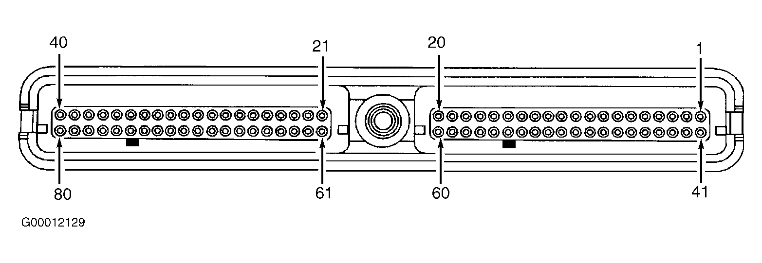
- Remove PCM/CRANK fuse, located in instrument panel fuse block. Using test light connected to ground, probe both PCM/CRANK fuse terminals inside instrument panel fuse block. If test light does not illuminate on either terminal, go to next step. If test light illuminates on one terminal, check for open or high resistance in Purple wire between Clear 80-pin PCM connector C2 terminal No. 23 and appropriate PCM/CRANK fuse terminal. See Fig 1
. See WIRING DIAGRAMS
. Repair as necessary and retest operation. If Purple wire checks okay, go to step 12
.
- Gain access to Black 48-pin in-line harness connector C201, located near base of steering column. Connect test light (backprobe) between ground and Black 48-pin in-line harness connector C201 terminal D1 (Yellow wire). See Fig 2
. Turn ignition switch to START position. If test light does not illuminate, go to step 16
. If test light illuminates, repair open in Yellow wire between Black 48-pin in-line harness connector C201 terminal D1 and appropriate PCM/CRANK fuse terminal. Retest operation.
- Check for open or high resistance in Yellow/Black wire between crank relay control circuit cavity No. 86 and Clear 80-pin PCM connector C2 terminal No. 76. Repair as necessary and retest operation. If Yellow/Black wire checks okay, go to step 17
.
- Check for open or high resistance in supply voltage circuit to starter solenoid (Purple wire). Repair as necessary and retest operation. If Purple wire checks okay, go to step 18
.
- Check operation and adjustment of PNP switch. See appropriate AUTOMATIC TRANSMISSION SERVICING article in AUTOMATIC TRANSMISSIONS. Check for poor connection to PNP switch. Repair as necessary and retest operation. If PNP switch connection and adjustment are okay, go to step 22
.
- Check for poor connections at crank relay. Repair as necessary and retest operation. If crank relay connections are okay, go to step 23
.
- Check for poor connections at Black 48-pin in-line harness connector C201. Repair as necessary and retest operation. If Black 48-pin in-line harness connector C201 connections are okay, go to step 24
.
- Check for poor connection at Clear 80-pin PCM connector C2. Repair as necessary and retest operation. If PCM connection is okay, go to step 25
.
- Check for poor connections at starter solenoid. Repair as necessary and retest operation. If starter solenoid connections are okay, go to step 26
.
- Repair open or high resistance in Red wire between crank relay cavity No. 30 and fusible link "C" connected to starter solenoid (crank relay switch feed circuit). Retest operation.
- Repair short to ground in Purple wire between crank relay cavity No. 87 and starter solenoid "S" terminal. Retest operation.
- Repair open in Orange/Black wire between PNP switch connector C1 terminal "E" and crank relay coil input circuit cavity No. 85. Retest operation.
- Replace PNP switch and retest operation. See appropriate AUTOMATIC TRANSMISSION SERVICING article in AUTOMATIC TRANSMISSIONS.
- Replace crank relay and retest operation.
- Replace ignition switch. See appropriate STEERING COLUMN SWITCHES article in ACCESSORIES & EQUIPMENT. Retest operation.
- Replace PCM. See appropriate REMOVAL, OVERHAUL & INSTALLATION article in ENGINE PERFORMANCE. Retest operation.
- Replace starter assembly. See STARTER
under REMOVAL & INSTALLATION. Retest operation.
 Courtesy of GENERAL MOTORS CORP.
 Courtesy of GENERAL MOTORS CORP.