- Turn the key to the LOCK position and remove the key.
NOTE:
The wheels of the vehicle must be straight ahead and the steering column in he LOCK position before disconnecting the steering column or intermediate shaft from the steering gear. Failure to do so will cause the coil assembly in the steering column to become uncentered which will cause damage to the coil assembly.
- Lock the steering column in the straight ahead position.
- Attempt to turn the steering wheel in order to verify the steering column is locked.
- Disable the supplemental inflatable restraint system. Refer to SIR DISABLING AND ENABLING ZONE 3
in SIR.
- Raise and support the vehicle. Refer to LIFTING & JACKING VEHICLE
in General Information.
- Remove the skid plate, if equipped.
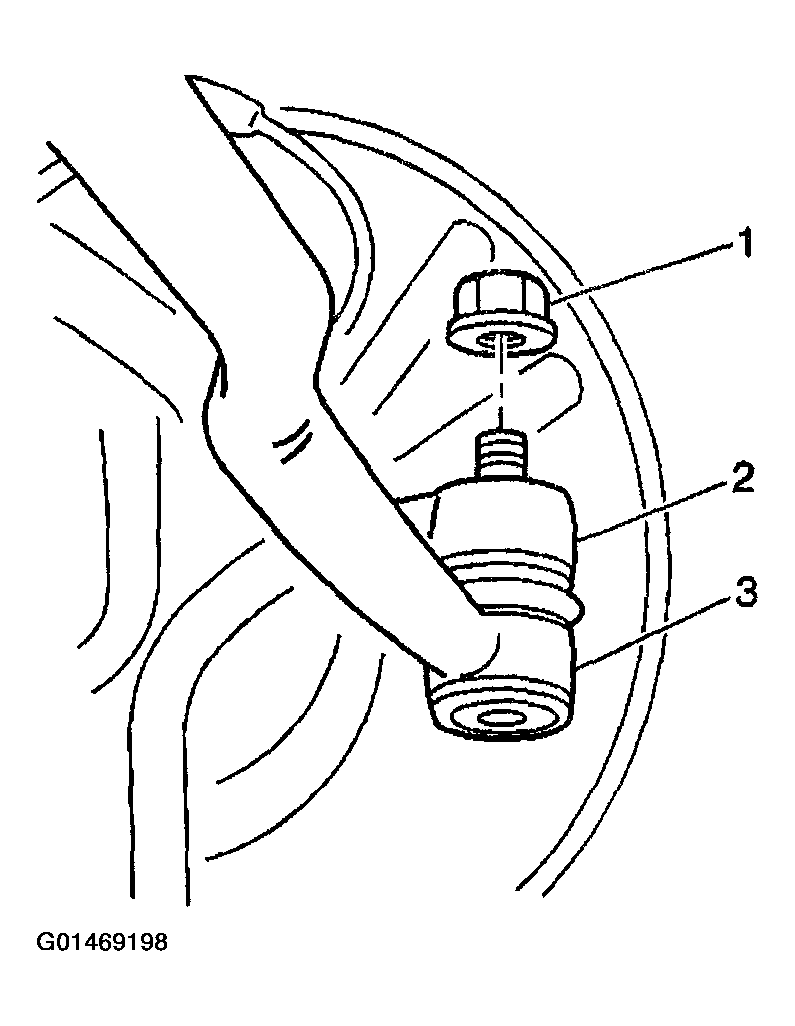
- Remove the left outer tie rod nut (1) from the knuckle (2).
 Courtesy of GENERAL MOTORS CORP.
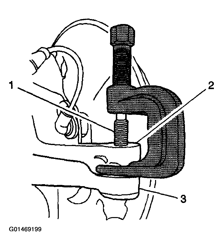
- Use J 6627-A in order to remove the tie rod end (3) from the knuckle (2).
- Remove the right outer tie rod nut from the knuckle.
- Use J 6627-A in order to remove the tie rod end from the knuckle.
- Place a drain pan or a suitable container under the steering gear.
 Courtesy of GENERAL MOTORS CORP.
IMPORTANT:
The first design banjo bolt style fitting utilizes 2 gaskets. The second design flare nut style fitting utilizes seals.
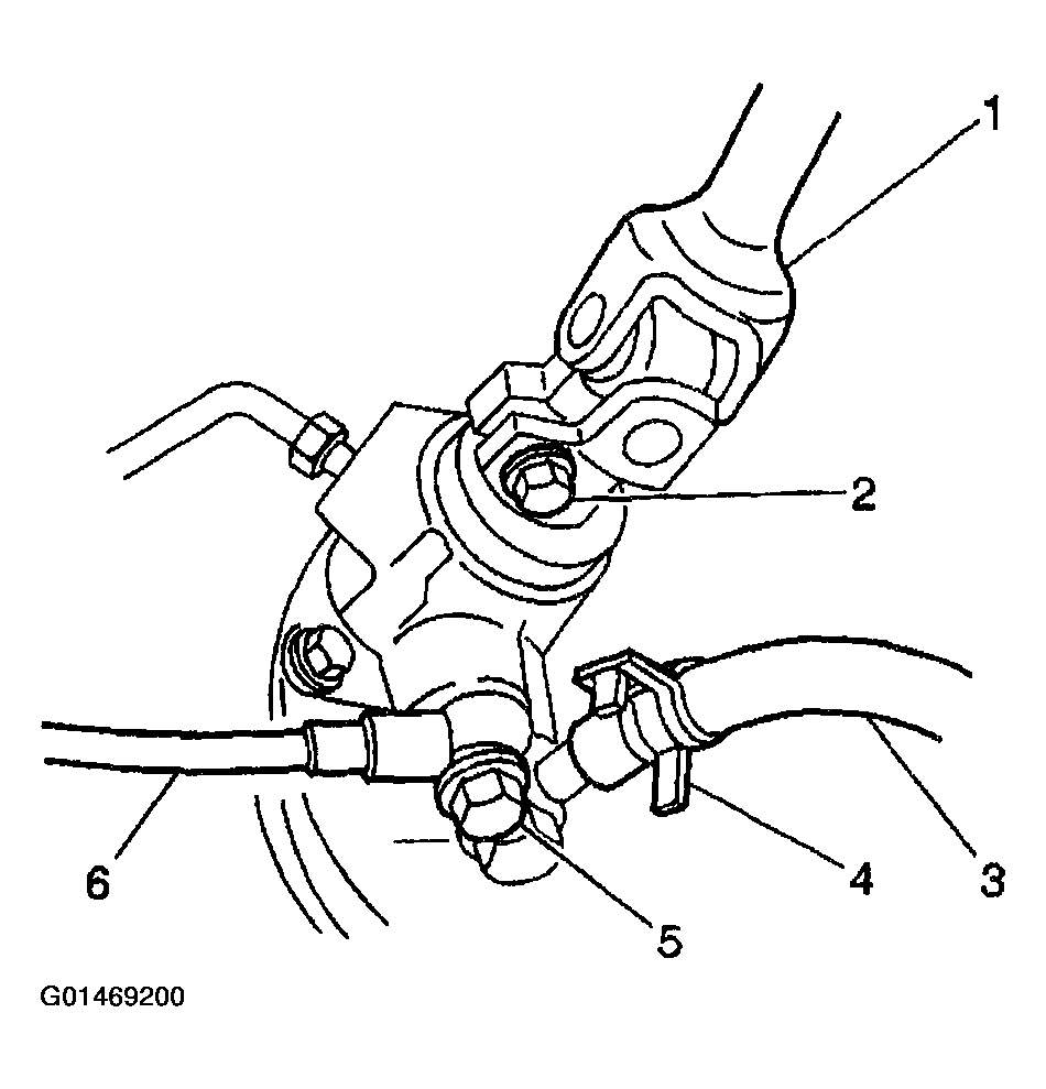
- Remove the power steering gear inlet hose fitting (5) from the power steering gear.
- Remove the power steering gear inlet hose (6) and the 2 gaskets, if equipped, from the steering gear.
- Loosen the hose clamp and remove the power steering fluid reservoir hose (3) from the steering gear.
- Plug the hoses in order to prevent the fluid from escaping.
- Using paint, place match marks on the lower steering shaft (1) and on the steering gear housing.
 Courtesy of GENERAL MOTORS CORP.
- Remove the clamp bolt (2) from the lower steering shaft.
- Disconnect the lower steering shaft from the steering gear.
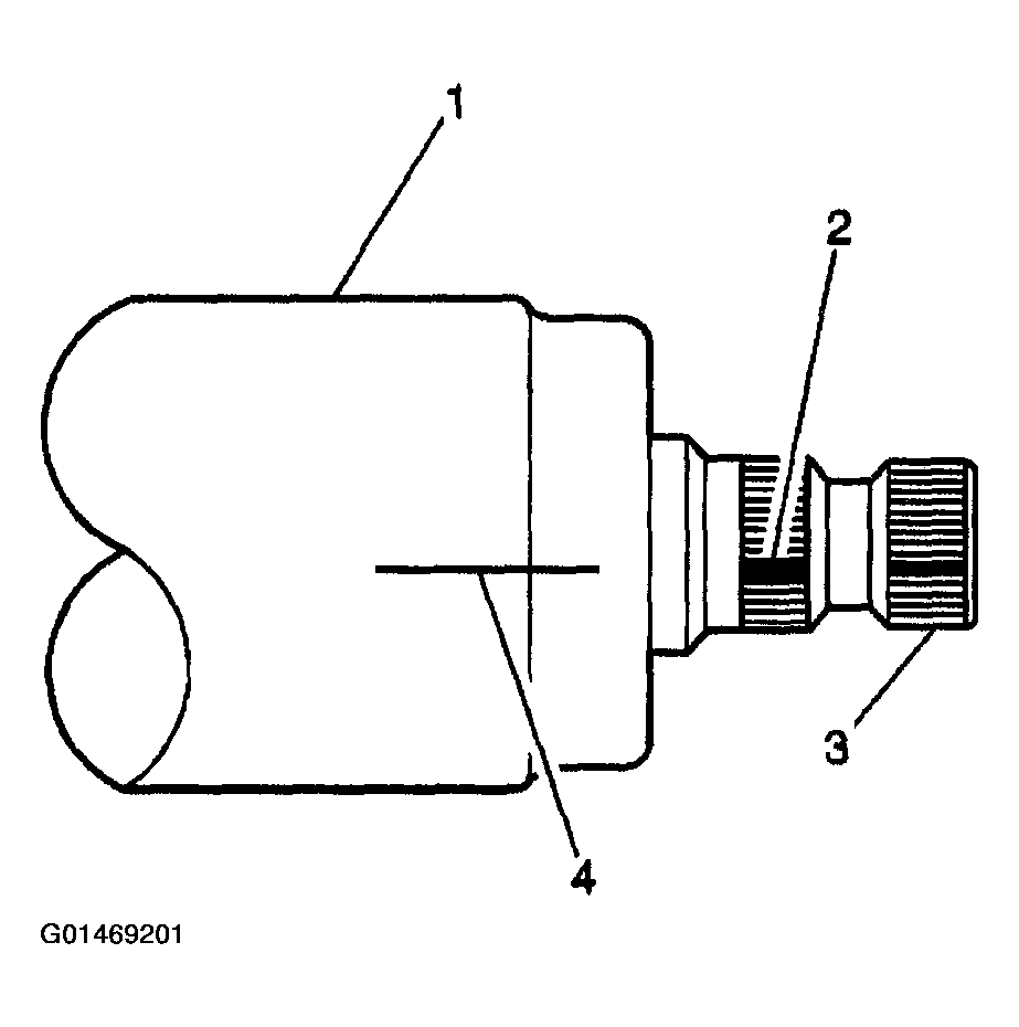
- Using paint, place match marks (2,4) on the pinion shaft (3) and on the steering gear housing (1).
 Courtesy of GENERAL MOTORS CORP.
IMPORTANT:
Do NOT disassemble the power steering gear.
- Remove the 4 steering gear mounting bolts (1).
- Remove the steering gear with the insulators and the brackets from the vehicle.
- Remove the 2 brackets from the steering gear.
- Remove the 2 insulators from the steering gear.
- Place a match mark on the left inner tie rod thread and the right inner tie rod thread, indicating the positions of the tie rod lock nuts.
- Loosen the 2 tie rod lock nuts and remove the 2 outer tie rod ends from the inner tie rods.
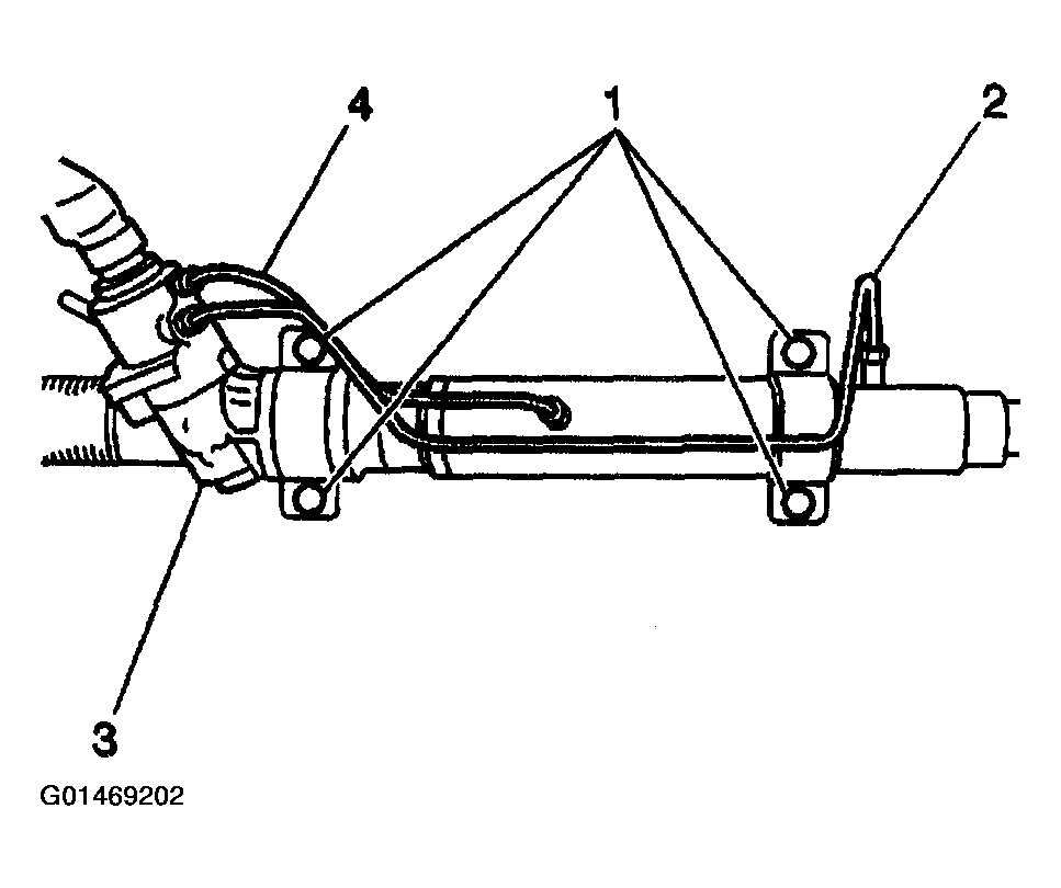 Courtesy of GENERAL MOTORS CORP.