Removal Procedure
- Raise the vehicle. Refer to Lifting and Jacking the Vehicle
in General Information.
- Spray penetrating oil on the exposed threads of both lower ball joint bolts to facilitate their removal later in this procedure.
- Lower the vehicle.
- Remove the air intake duct from the throttle body and air cleaner assembly.
- Remove the battery cover and disconnect the negative battery cable. Refer to Battery Negative Cable Disconnect/Connect Procedure
in Engine Electrical.
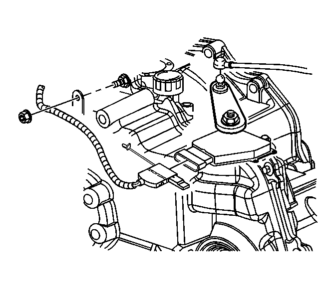 Courtesy of GENERAL MOTORS CORP.
- Disconnect the transaxle wiring harness from the transaxle and the park/neutral position (PNP) switch.
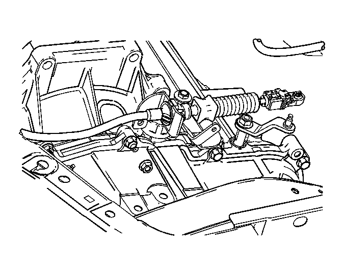 Courtesy of GENERAL MOTORS CORP.
- Remove the shift cable bracket and shift cable from the lever.
- Remove the transmission wiring harness from the retainer on the transmission.
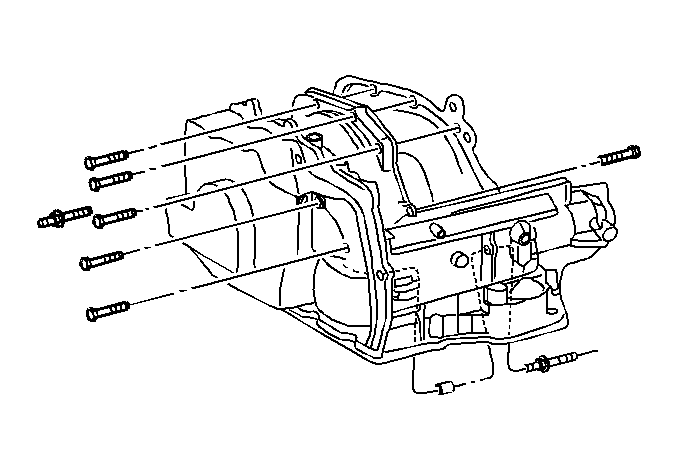 Courtesy of GENERAL MOTORS CORP.
- Remove the upper transmission to engine bolts and stud.
- Install the engine support fixture. Refer to Engine Support Fixture
in Engine Mechanical.
- Support the radiator and condenser from above using the condenser tabs on each side.
- Raise and support the vehicle. Refer to Lifting and Jacking the Vehicle
in General Information.
- Remove the front wheel and tire assemblies. Refer to Tire and Wheel Removal and Installation
in Tires and Wheels.
- Remove the steering gear intermediate shaft.
- Separate the control arm from the frame and the outer tie rod ends from the steering knuckles. Support the lower control arm with mechanics wire or a similar method.
- Remove the frame. Refer to Frame Replacement (W/L61)
or Frame Replacement (W/LX9)
in Frame and Underbody.
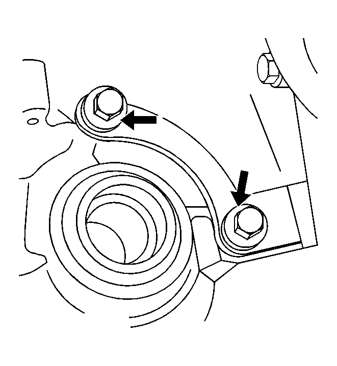 Courtesy of GENERAL MOTORS CORP.
- Remove the 3 bolts from the transmission brace near the right axle shaft.
- Remove the oil pan to bell housing bracket (3 bolts).
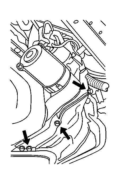 Courtesy of GENERAL MOTORS CORP.
- Remove the flywheel inspection cover.
- Remove the starter. Refer to Starter Motor Replacement (L61)
or Starter Motor Replacement (LX9)
in Engine Electrical.
- Mark the relationship of the flywheel to the torque converter for reassembly.
- Remove the torque converter to flywheel bolts.
- Remove the transmission cooler lines by removing the nut holding the bracket to the transaxle case.
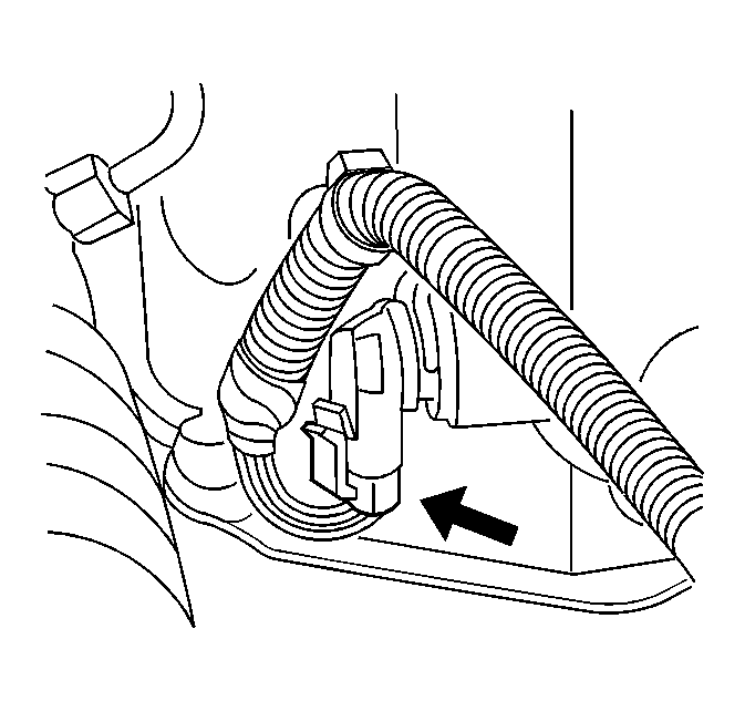 Courtesy of GENERAL MOTORS CORP.
- Disconnect the vehicle speed sensor (VSS) wiring harness from the sensor.
- Disconnect the rear 02 sensor harness from the bracket on the steering gear.
- Disconnect the wheel drive shafts from the transaxle. Refer to Wheel Drive Shaft Replacement
in Wheel Drive Shafts
- Remove the front transmission mount bracket from the transmission.
- Use a transmission jack to support the transmission.
- Remove the remaining bell housing bolts and studs and separate the transmission from the engine.
- Lower the transmission with the transmission jack far enough to remove the transmission.
- If the transmission is being replaced or installed in a holding fixture, remove the rear transmission mount bracket from transmission.
- Remove the PNP switch from the transmission.