Installation Procedure
 Courtesy of GENERAL MOTORS COMPANY
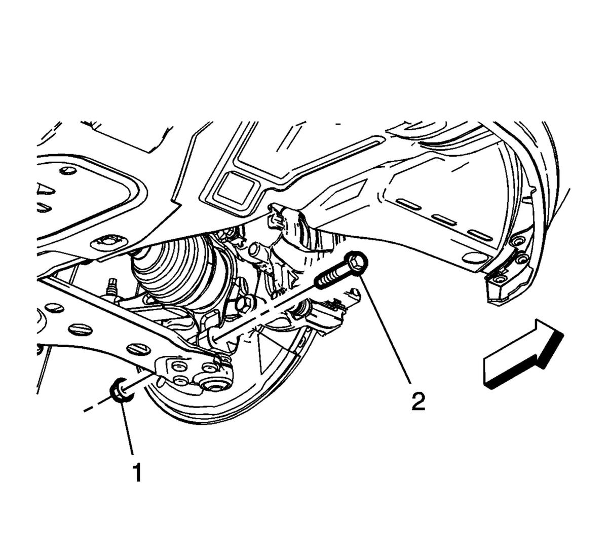
- Push the front brake corner forward and position the lower control arm (3) on the vehicle.
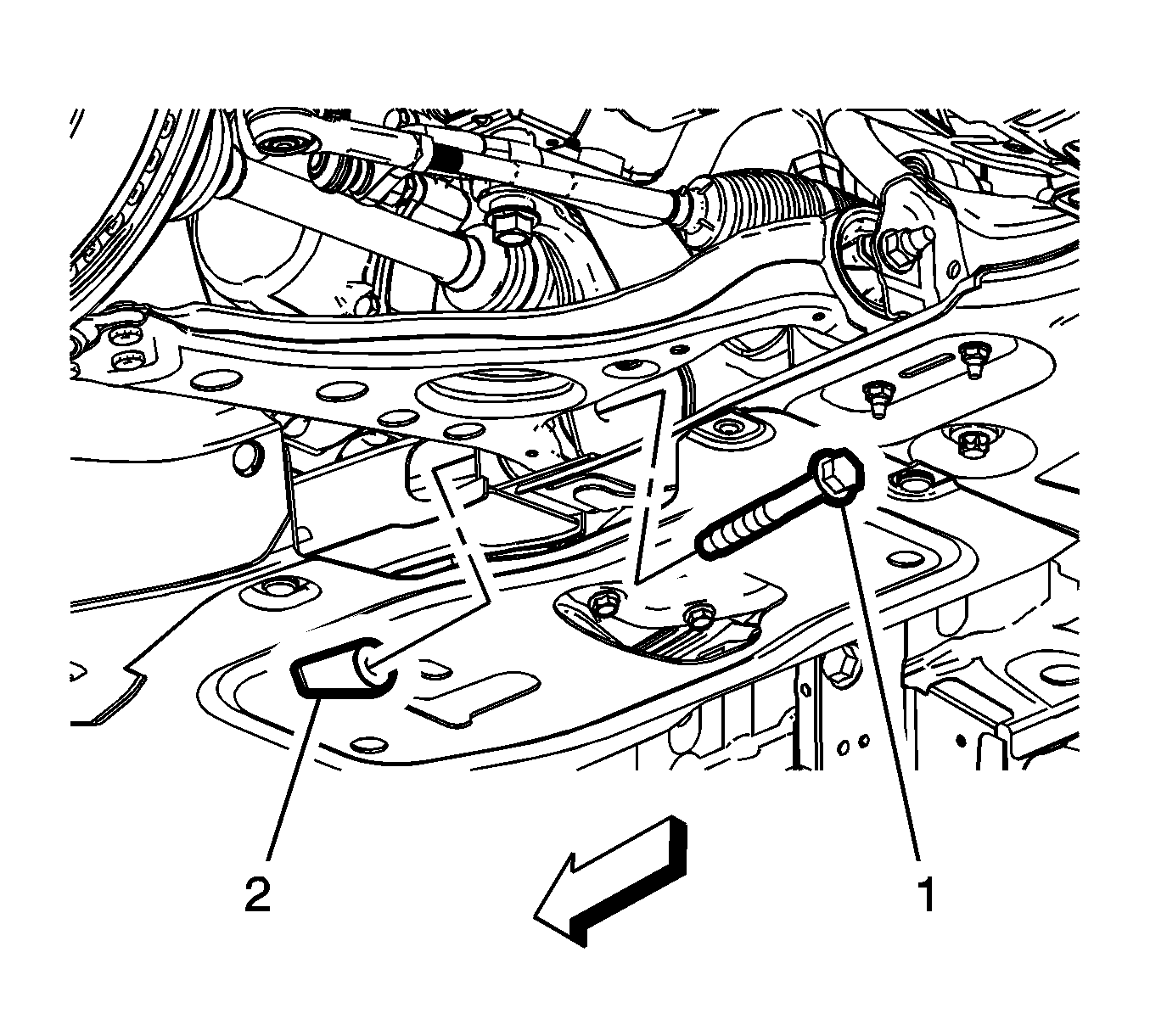
- Install the front lower control arm rear nut (1) and front lower control arm rear bolt (2) and tighten by hand.
 Courtesy of GENERAL MOTORS COMPANY
- Install the front lower control arm front bolt (1) and front lower control arm front nut (2) and tighten by hand.
 Courtesy of GENERAL MOTORS COMPANY
- Install the steering knuckle nut (1) and steering knuckle bolt (2) and tighten the nut to 37 N.m (27 lb ft).
- After tightening, loosen the steering knuckle nut (1) 120 degrees.
- After loosening, tighten the steering knuckle nut (1) to 30 N.m (22 lb ft) + (30-45 degrees).
 Courtesy of GENERAL MOTORS COMPANY
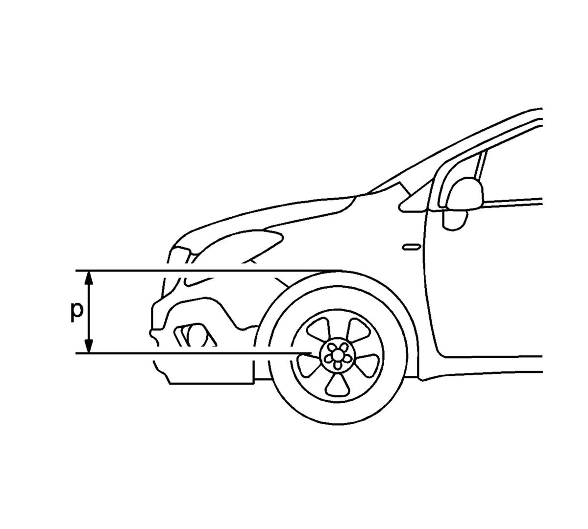
- Support the lower control arm with a hydraulic jack and lift the control arm until the previously recorded measurement (p) is achieved.
Courtesy of GENERAL MOTORS COMPANY
- Tighten the front lower control arm front bolt (1) to 115 N.m (85 lb ft).
- After tightening, loosen the front lower control arm front bolt (1) 720 degrees.
- After loosening, tighten the front lower control arm front bolt (1) to 70 N.m (52 lb ft) + (90-105 degrees).
Courtesy of GENERAL MOTORS COMPANY
- Tighten the front lower control arm rear bolt (2) to 80 N.m (59 lb ft) + (60-75 degrees).
- Install the tire and wheel assembly. Refer to Tire and Wheel Removal and Installation
.