- Before continuing, lubricate the cylinder head bore with clean engine oil. Refer to Adhesives, Fluids, Lubricants and Sealers
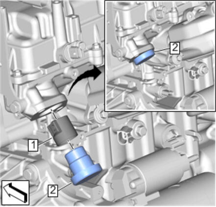
- Lubricate the valve lifter follower (1) with clean engine oil and install it into the cylinder head bore. Refer to Adhesives, Fluids, Lubricants and Sealers
 Courtesy of GENERAL MOTORS COMPANY
- Install the EN-51365
alignment gauge (2) and turn the crankshaft until the camshaft lobe is at the base circle position.
NOTE:
- The camshaft MUST be at the base circle position before the fuel pump is installed.
- At the base circle position, the EN-51365
alignment gauge will sit flush with the cylinder head.
- Remove the EN-51365
alignment gauge (2) and valve lifter follower (1).
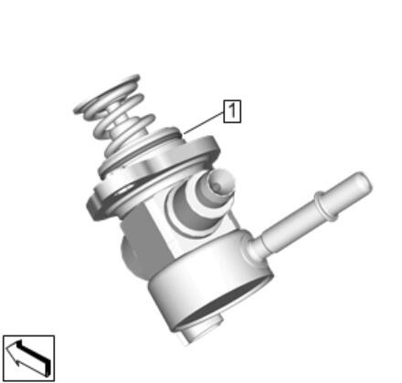
- Lubricate the NEW fuel pump housing seal (1) with clean engine oil and install it on the fuel pump. Refer to Adhesives, Fluids, Lubricants and Sealers
 Courtesy of GENERAL MOTORS COMPANY
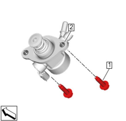
- Install the NEW fuel pump bolts (1) through the fuel pump bolt retainers (2).
 Courtesy of GENERAL MOTORS COMPANY
CAUTION:
This vehicle is equipped with torque-to-yield or single use fasteners. Install a NEW torque-to-yield or single use fastener when installing this component. Failure to replace the torque-to-yield or single use fastener could cause damage to the vehicle or component.
NOTE:
- ALWAYS make sure the fuel pump bolt retainers are present before installing the fuel pump bolts.
- If ANY fuel pump bolt retainers are missing or NOT suitable for reuse, replace the retainers as necessary.
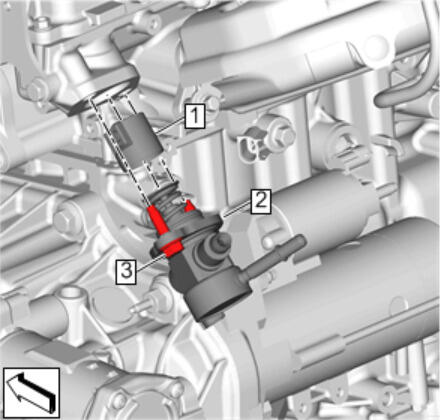
- Lubricate the valve lifter follower (1) with clean engine oil and install it into the cylinder head bore. Refer to Adhesives, Fluids, Lubricants and Sealers
 Courtesy of GENERAL MOTORS COMPANY
- Install the fuel pump assembly (2) into the cylinder head and start the fuel pump bolts (3) by hand.
- Tighten the NEW fuel pump bolts (3) to 25 N.m (18 lb ft).
CAUTION:
Alternately hand-tighten the fuel pump bolts one turn at a time until the pump is fully seated. Trying to draw down the pump without even side-to-side tightening may result in pump plunger damage.
- Install the fuel pump insulator (1).
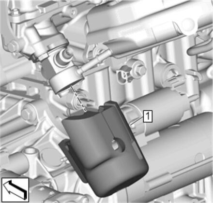 Courtesy of GENERAL MOTORS COMPANY
- Position the engine wiring harness bracket (3).
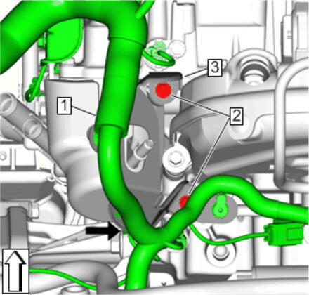 Courtesy of GENERAL MOTORS COMPANY
- Install the engine wiring harness bracket bolts (2) and tighten to 9 N.m (80 lb in).
- Connect the engine wiring harness electrical connectors (1).
- Install the NEW fuel feed intermediate pipe. Refer to Fuel Feed Intermediate Pipe Replacement
NOTE:
High pressure fuel feed pipes are one time use only. ALWAYS install a NEW high pressure fuel feed pipe if the pipe is removed OR the fittings are loosened.
- Connect the fuel feed front pipe to the fuel pump. Refer to Fuel Feed Front Pipe Replacement
- Connect the battery negative cable. Refer to Battery Negative Cable Disconnection and Connection (without KL9)Battery Negative Cable Disconnection and Connection (with KL9)
- Inspect for leaks using the following procedure:
- Turn ON the ignition with the engine OFF for 2 seconds.
- Turn OFF the ignition for 10 seconds.
- Turn ON the ignition with the engine OFF.
- Inspect for fuel leaks.
- Install the charge air cooler outlet air tube to the throttle body. Refer to Charge Air Cooler Outlet Air Tube Replacement
- Intake Manifold Cover - Install Intake Manifold Cover Replacement
- Use a scan tool to perform any necessary learn procedures. Refer to K20 Engine Control Module: Programming and Setup