Anti-Theft System: Testing
- Cycle the ignition from "LOCK" to "ACCESSORY" position 3 times. Leave ignition in the "ACCESSORY" position. If park and tail lights do not flash, proceed to step 6). If horn does not sound 2 times, proceed to step 5).
- If park and tail lights flash and horn sounds 2 times, vehicle is in self-diagnostic mode. Check indicator "SET" light. If light is not flashing, check for defective bulb or circuitry. If light is flashing, turn ignition to the "OFF" position.
- Check switches using system diagnosis. See BCC - TESTS W/O CODES
in ENGINE PERFORMANCE section. If switches test bad, repair as necessary and retest system. If switches test good, turn ignition on and wait 5 seconds. If indicator "SET" light remains off, turn ignition off. "Arm" system by closing and locking door using the power door lock switch. Test is complete if system operates correctly.
- If indicator "SET" light remained on in step 3), problem is in wiring harness between anti-theft control module and SBEC. See appropriate chassis wiring diagram in WIRING DIAGRAMS
article. If system will not "arm" suspect that SBEC module has recently been replaced. Crank engine 20 times and re-test system.
- If horn did not sound 2 times in step 1), check fuse and replace if blown. If fuse is not blown, check decklid switch for continuity and replace if switch is open. If switch is okay, check wiring between switch and anti-theft control module. See Figure
. If wiring is okay, replace anti-theft control module.
- If park and tail lights did not flash in step 1), check fuse and replace if blown. If fuse is not blown, check anti-theft control module connector from wiring harness side for battery voltage at Pins No. 6, 14, 18 and 19. If wiring is okay, replace anti-theft control module.
CONNECTOR PIN CHART
| Pin No. |
Wire Color |
Function |
Voltage |
| 1 |
Black/Green |
Ground |
Zero |
| 2 |
White |
Data Bus (-) |
2.5 |
| 3 |
Tan/Black |
Hood Ajar |
8.5 |
| 4 |
Black |
Data Bus (+) |
2.5 |
| 5 |
Tan |
LF Door Ajar |
5 |
| 5 |
White/Tan |
All Doors |
5 |
| 6 |
Blue |
Ign. Feed |
12 |
| 7 |
Orange |
LR Door Ajar |
5 |
| 8 |
Green/Orange |
RF Door Lock |
12 |
| 9 |
Black/Orange |
Ind. Set Light |
12 |
| 10 |
Black/Green |
Ground |
Zero |
| 11 |
Pink/Purple |
Power Door Lock |
12 |
| 12 |
Black/Red |
Horn Relay (-) |
12 |
| 13 |
Orange/White |
Power Door Lock |
12 |
| 14 |
Black/Yellow |
Tail/Park Lights |
12 (on) |
| 15 |
Green/Orange |
LF Door Key |
12 |
| 16 |
Tan/Red |
RF Door Ajar |
5 |
| 17 |
Purple/Yellow |
Trunk Lock (-) |
12 |
| 18 |
Red |
Battery Feed |
12 |
| 19 |
Blue |
Ignition Feed |
12 |
| 20 |
Tan/Yellow |
RR Door Ajar |
5 |
| 21 |
Pink/Black |
Tail/Park |
12 |
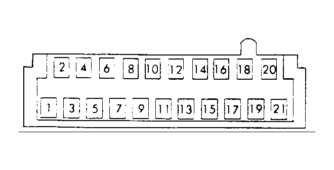 Courtesy of CHRYSLER MOTORS.