Connector Identification
CONNECTOR IDENTIFICATION DIRECTORY
| Connector |
Figure |
| ABS Boost Pressure Transducer |
9 |
| ABS Dual-Function Pressure Switch |
10 |
| ABS Modulator |
11 |
| ABS Primary Pressure Transducer |
9 |
| ABS Pump/Motor |
12 |
| ABS Pump/Motor Relay |
4 |
| ABS Relay |
7 |
| ABS Switch/Transducer |
13 |
| ABS Wheel Speed Sensor |
14 |
| ABS 8-Pin Body Connector |
15 |
| ANTI-LOCK Warning Light Relay |
7 |
| CCD Data Link Connector |
8 |
| Controller Anti-Lock Brake (CAB) |
6 |
 Courtesy of CHRYSLER CORP.
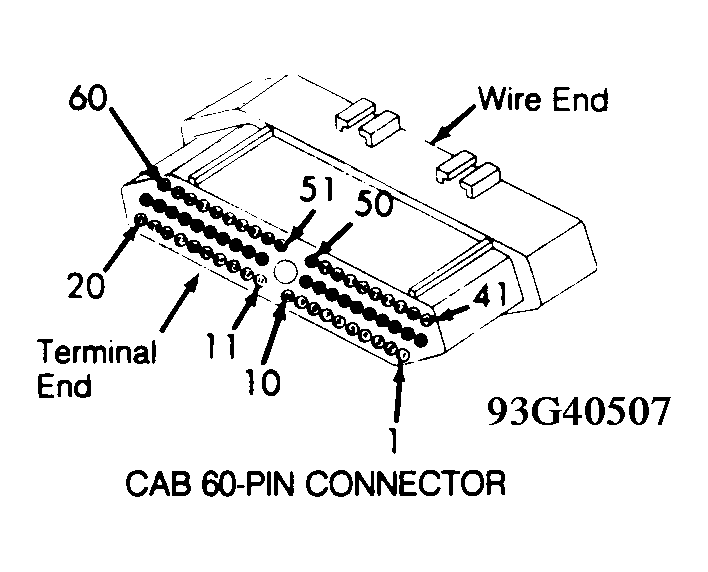
 CAB 60-PIN CONNECTOR
| Terminal |
Circuit |
Function |
| 1 |
YEL/DK BLU |
RR ABS Wheel Sensor + |
| 2 |
YEL |
ABS Wheel Sensor - |
| 3 |
LT GRN/DK BLU |
LR Wheel Sensor + |
| 4 |
LT GRN |
LR Wheel Sensor - |
| 5 |
BLK |
Ground |
| 6 |
WHT/DK BLU |
RF ABS Wheel Sensor + |
| 7 |
WHT |
RF ABS Wheel Sensor - |
| 8 |
RED/DK BLU |
LF ABS Wheel Sensor + |
| 9 |
RED |
LF ABS Wheel Sensor - |
| 10 |
RED/BLK |
Transducer Return |
| 11 |
WHT/VIO |
Diagnostic ABS (Signal Data In) |
| 12 |
ORG |
Diagnostic ABS (Signal Data Out) |
| 13 |
WHT/TAN |
Stoplight Signal To Lights |
| 14 |
GRY/BLK |
Brake Fluid Level/Park Brake |
| 15 |
LT GRN/ORG |
ABS Warning Light |
| 16 |
GRY/RED |
Low Fluid Output Sense |
| 17 |
RED |
Low Accumulator |
| 18 |
WHT/ORG |
Primary Pressure/DPA |
| 19 |
DK BLU |
Boost Pressure Transducer Sensor |
| 20 - 41 |
Not Used |
Not Used |
| 42 |
BRN/WHT |
LF Build Valve |
| 43 |
DK GRN/BLK |
LF Decay Valve |
| 44 |
Not Used |
Not Used |
| 45 |
WHT/LT GRN |
LF Isolation Valve |
| 46 |
BRN/RED |
RF Build Valve |
| 47 |
RED/LT BLU |
12-Volt ABS Solenoid Feed |
| 48 |
DK GRN/WHT |
RF Decay Valve |
| 49 |
WHT/TAN |
RF Isolation Valve |
| 50 |
RED/LT BLU |
Solenoid 12-Volt Feed |
| 51 |
WHT/BLK |
LR Isolation Valve |
| 52 |
BRN/TAN |
Rear Build Valve |
| 53 |
Not Used |
Not Used |
| 54 |
DK GRN/ORG |
Rear Decay Valve |
| 55 |
WHT/PNK |
RR Isolation Valve |
| 56 |
Not Used |
Not Used |
| 57 |
BRN/BLK |
ABS Relay Control |
| 58 |
GRY/LT BLU |
Transducer Feed (5-Volt) |
| 59 |
Not Used |
Not Used |
| 60 |
DK BLU |
Ignition Start/Run |
 Courtesy of CHRYSLER CORP.
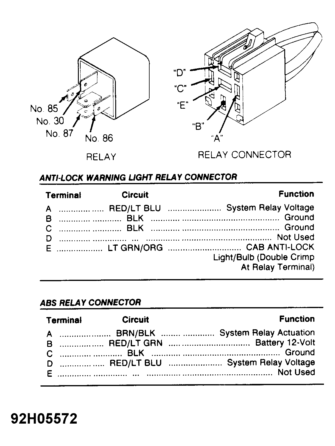
 ANTI-LOCK WARNING LIGHT RELAY CONNECTOR
| Terminal |
Circuit |
Function |
| A |
RED/LT BLU |
System Relay Voltage |
| B |
BLK |
Ground |
| C |
BLK |
Ground |
| D |
Not Used |
Not Used |
| E |
LT GRN/ORG |
CAB ANTI-LOCK |
| ** |
*** |
Light/Bulb (Double Crimp |
| ** |
*** |
At Relay Terminal) |
ABS RELAY CONNECTOR
| Terminal |
Circuit |
Function |
| A |
BRN/BLK |
System Relay Actuation |
| B |
RED/LT GRN |
Battery 12-Volt |
| C |
BLK |
Ground |
| D |
RED/LT BLU |
System Relay Voltage |
| E |
Not Used |
Not Used |
 Courtesy of CHRYSLER CORP.
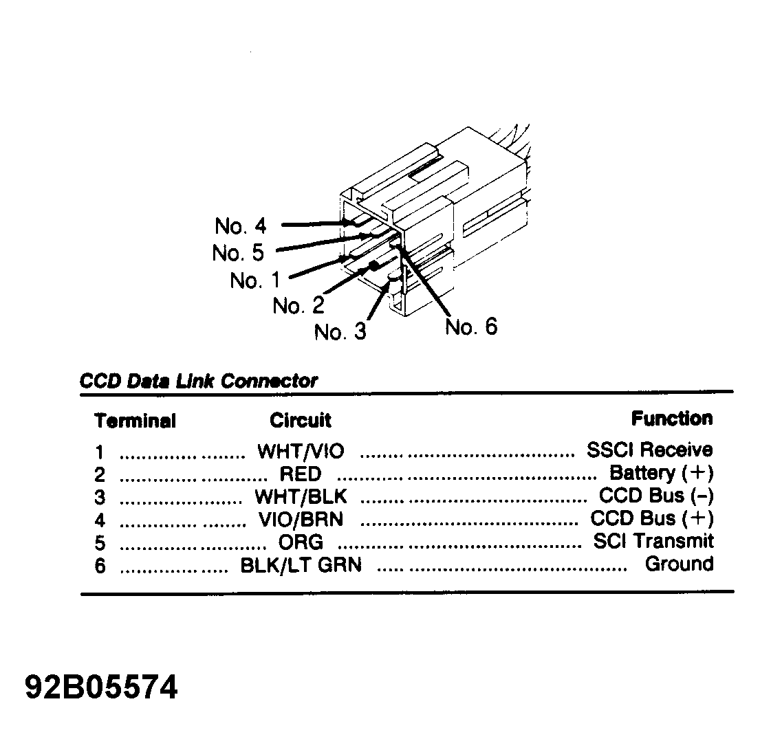
 CCD DATA LINK CONNECTOR
| Terminal |
Circuit |
Function |
| 1 |
WHT/VIO |
SSCI Receive |
| 2 |
RED |
Battery (+) |
| 3 |
WHT/BLK |
CCD Bus (-) |
| 4 |
VIO/BRN |
CCD Bus (+) |
| 5 |
ORG |
SCI Transmit |
| 6 |
BLK/LT GRN |
Ground |
 Courtesy of CHRYSLER CORP.
 Courtesy of CHRYSLER CORP.
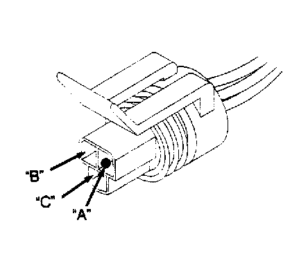
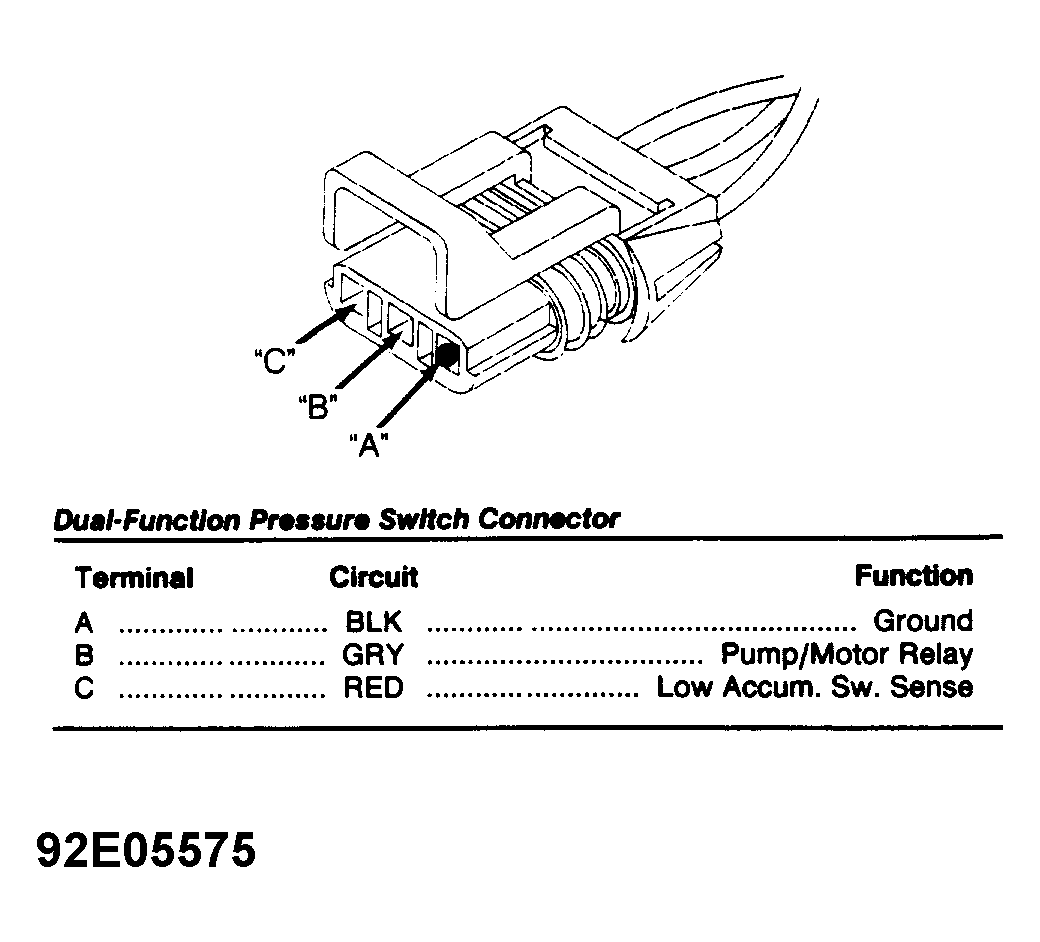
 DUAL-FUNCTION PRESSURE SWITCH CONNECTOR
| Terminal |
Circuit |
Function |
| A |
BLK |
Ground |
| B |
GRY |
Pump/Motor Relay |
| C |
RED |
Low Accum. Sw. Sense |
 Courtesy of CHRYSLER CORP.
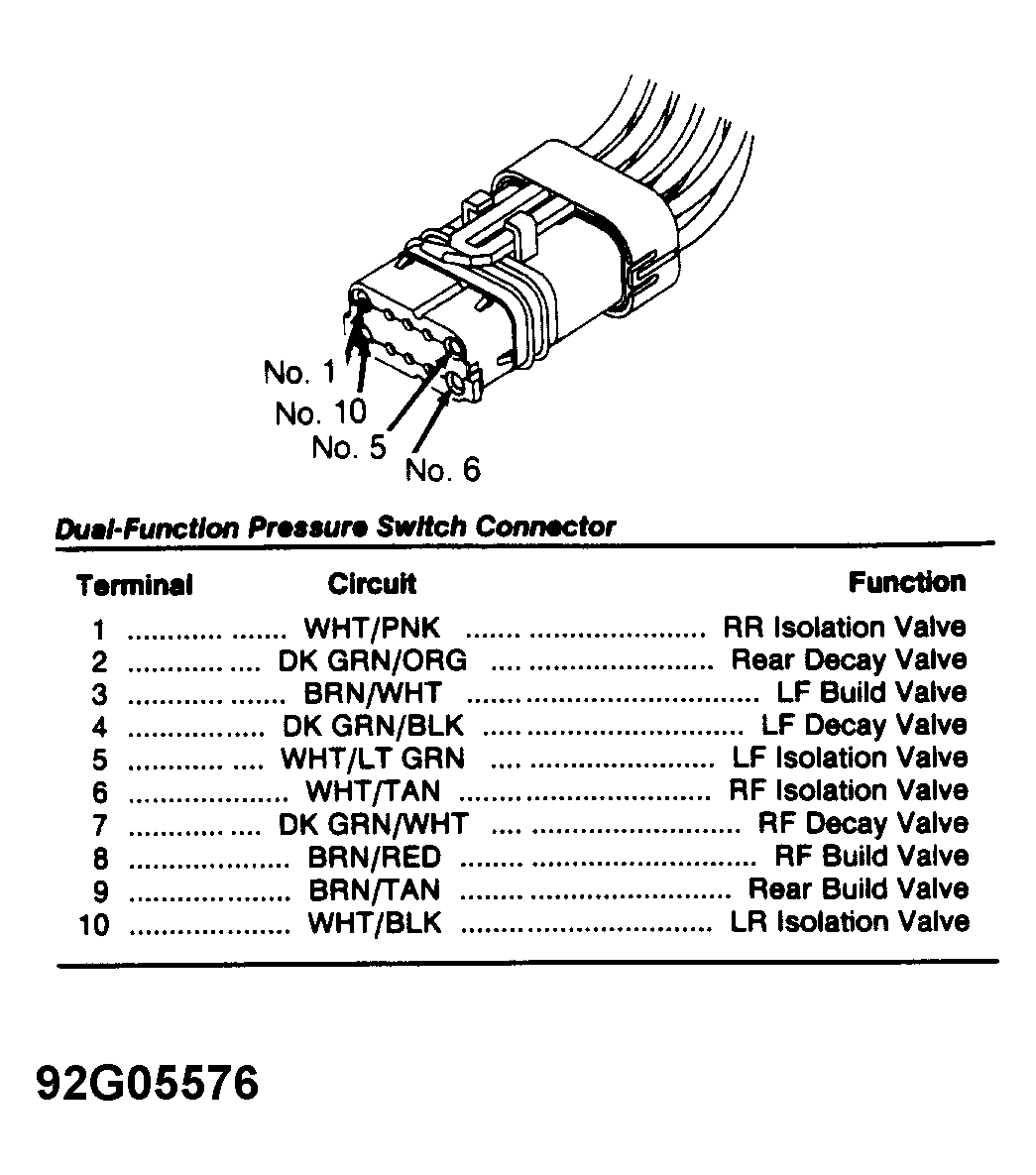
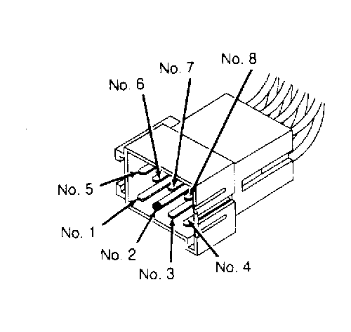
 DUAL-FUNCTION PRESSURE SWITCH CONNECTOR
| Terminal |
Circuit |
Function |
| 1 |
WHT/PNK |
RR Isolation Valve |
| 2 |
DK GRN/ORG |
Rear Decay Valve |
| 3 |
BRN/WHT |
LF Build Valve |
| 4 |
DK GRN/BLK |
LF Decay Valve |
| 5 |
WHT/LT GRN |
LF Isolation Valve |
| 6 |
WHT/TAN |
RF Isolation Valve |
| 7 |
DK GRN/WHT |
RF Decay Valve |
| 8 |
BRN/RED |
RF Build Valve |
| 9 |
BRN/TAN |
Rear Build Valve |
| 10 |
WHT/BLK |
LR Isolation Valve |
 Courtesy of CHRYSLER CORP.
 Courtesy of CHRYSLER CORP.
 Courtesy of CHRYSLER CORP.
 Courtesy of CHRYSLER CORP.