Power Mirror Motor Test
- Remove power mirror switch from mounting position. Disconnect wiring harness connector at switch. In case of memory mirrors (Green 8-pin mirror switch connector and memory switch in driver's door panel), wiring disconnects from cowl top harness rather than mirror harness.
- Connect one end of jumper wire to 12-volt source. Connect one end of second jumper wire to a good body ground. Connect remaining end of each jumper wire to specified pins on harness side (not switch side). See appropriate POWER MIRROR MOTOR TEST
. If mirror operation is not as specified in table, check circuit for broken or shorted wire. If wiring is okay, replace mirror assembly as necessary.
POWER MIRROR MOTOR TEST
| Apply 12 Volts To Pin No. |
Ground Pin No. |
Operation (Right) |
Operation (Left) |
| Switch Connector |
| 6 |
5 |
Up |
N/A |
| 4 |
5 |
N/A |
Up |
| 5 |
6 |
Down |
N/A |
| 5 |
4 |
N/A |
Down |
| 5 |
7 |
Right |
N/A |
| 5 |
8 |
N/A |
Right |
| 7 |
5 |
Left |
N/A |
| 8 |
5 |
N/A |
Left |
| Door Connector |
| 1 |
5 |
Up |
Up |
| 5 |
1 |
Down |
Down |
| 4 |
6 |
Right |
Right |
| 6 |
4 |
Left |
Left |
| 2 |
3 |
|
|
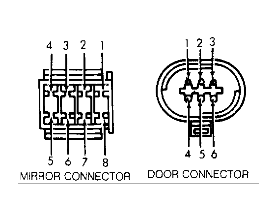 Courtesy of CHRYSLER CORP.