DTC P1595: Speed Control Solenoid Circuits: Testing
- Turn ignition on. Turn speed control on. Using scan tool, actuate speed control vent solenoid. Speed control vent solenoid is an integral part of speed control servo. If speed control servo clicks, go to next step. If speed control servo does not click, go to step 13
.
- Using scan tool, actuate speed control vacuum solenoid. Speed control vacuum solenoid is an integral part of speed control servo. If speed control servo clicks, go to next step. If speed control servo does not click, go to step 6
.
- Turn ignition off. Inspect wiring and connectors for damage. If wiring and connectors are okay, go to next step. If wiring and connectors are not okay, repair or replace as necessary.
- Turn ignition on. Turn speed control on. Using scan tool, actuate speed control vent solenoid. Wiggle wiring harness between speed control servo, brakelight switch and Powertrain Control Module (PCM). PCM is located to left of Power Distribution Center (PDC) in engine compartment, next to air cleaner. If wiggling does not interrupt actuation, go to next step. If wiggling interrupted actuation, repair wiring harness as necessary where wiggling caused problem to appear.
- Using scan tool, actuate speed control vacuum solenoid. Wiggle wiring harness between speed control servo, brakelight switch and PCM. If wiggling does not interrupt actuation, test is complete. If wiggling interrupted actuation, repair wiring harness as necessary where wiggling caused problem to appear.
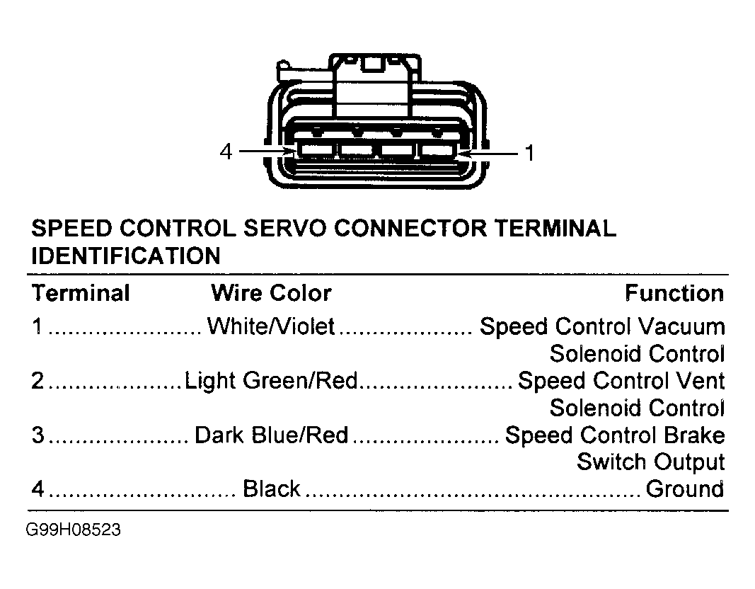
- Turn ignition off. Disconnect speed control servo harness connector. Inspect harness connector and clean/repair as necessary. Ensure brake pedal is not depressed. Turn ignition on. Turn speed control on. Measure voltage between ground and terminal No. 3 (Dark Blue/Red wire) at speed control servo harness connector. See Fig 1
. If voltage is less than 10 volts, go to next step. If voltage is 10 volts or more, go to step 14
.
- Turn ignition off. Disconnect brakelight switch harness connector. Turn ignition on. Turn speed control on. Measure voltage between ground and terminal No. 3 (Yellow/Pink wire) at brakelight switch harness connector. See Figure
. If voltage is 10 volts or more, go to next step. If voltage is less than 10 volts, go to step 10
.
- Turn ignition off. Check brakelight switch adjustment. If brakelight switch adjustment is okay, go to next step. If brakelight switch adjustment is not okay, adjust brakelight switch.
- Measure resistance between ground and terminal No. 3 (Dark Blue/Red wire) at speed control servo harness connector. If resistance is 5 ohms or more, go to step 23
. If resistance is less than 5 ohms, repair short to ground in Dark Blue/Red wire between brakelight switch and speed control servo.
- Measure resistance between ground and terminal No. 3 (Yellow/Pink wire) at brakelight switch harness connector. If resistance is 5 ohms or more, go to next step. If resistance is less than 5 ohms, repair short to ground in Yellow/Pink wire between brakelight switch and PCM.
- Disconnect Powertrain Control Module (PCM) harness connectors. PCM is located to left of Power Distribution Center (PDC) in engine compartment, next to air cleaner. Measure resistance in Yellow/Pink wire between terminal No. 3 at brakelight switch harness connector and terminal No. 5 at PCM harness connector C1. See Figure
and Figure
. If resistance is less than 5 ohms, go to next step. If resistance is 5 ohms or more, repair open in Yellow/Pink wire between brakelight switch and PCM.
- Connect PCM harness connectors. Connect speed control servo harness connector. Connect brakelight switch harness connector. Turn ignition on. Turn speed control on. Using scan tool, actuate speed control vent solenoid. Wiggle wiring harness between speed control servo, brakelight switch and Powertrain Control Module (PCM). If actuation is not interrupted, go to step 27
. If actuation is interrupted, repair wiring harness as necessary where wiggling caused problem to appear.
- Turn ignition off. Ensure brake pedal is not depressed. Turn speed control on. Measure voltage between ground and terminal No. 3 (Dark Blue/Red wire) at speed control servo harness connector. If voltage is 10 volts or more, go to next step. If voltage is less than 10 volts, go to step 20
.
- Turn ignition off. Measure resistance between ground and terminal No. 4 (Black wire) at speed control servo harness connector. If resistance is less than 5 ohms, go to next step. If resistance is 5 ohms or more, repair open in Black wire between speed control servo and ground. Ground point is located on driver's side strut tower.
- Disconnect Powertrain Control Module (PCM) harness connectors. PCM is located to left of Power Distribution Center (PDC) in engine compartment, next to air cleaner. Measure resistance in White/Violet wire between terminal No. 1 at speed control servo harness connector and terminal No. 56 at PCM harness connector C2. See Figure
and Fig 1
. If resistance is less than 5 ohms, go to next step. If resistance is 5 ohms or more, repair open in White/Violet wire between speed control servo and PCM.
- Measure resistance between ground and terminal No. 56 (White/Violet wire) at PCM harness connector C2. If resistance is 5 ohms or more, go to next step. If resistance is less than 5 ohms, repair short to ground in White/Violet wire between speed control servo and PCM.
- Measure resistance in Light Green/Red wire between terminal No. 2 at speed control servo harness connector and terminal No. 80 at PCM harness connector C2. If resistance is less than 5 ohms, go to next step. If resistance is 5 ohms or more, repair open in Light Green/Red wire between speed control servo and PCM.
- Measure resistance between ground and terminal No. 80 (Light Green/Red wire) at PCM harness connector C2. If resistance is 5 ohms or more, go to next step. If resistance is less than 5 ohms, repair short to ground in Light Green/Red wire between speed control servo and PCM.
- If no other potential causes are remaining, replace speed control servo.
- Turn ignition off. Disconnect brakelight switch connector. Inspect harness connector and clean/repair as necessary. Turn ignition on. Measure voltage between ground and terminal No. 3 (Yellow/Pink wire) at brakelight switch harness connector. See Figure
. If voltage is 10 volts or more, go to next step. If voltage is less than 10 volts, go to step 25
.
- Disconnect speed control servo harness connector. Inspect harness connector and clean/repair as necessary. Measure resistance between ground and terminal No. 3 (Dark Blue/Red wire) at speed control servo harness connector. If resistance is 5 ohms or more, go to next step. If resistance is less than 5 ohms, repair short to ground in Dark Blue/Red wire between speed control servo and brakelight switch.
- Turn ignition off. Check brakelight switch adjustment. If brakelight switch adjustment is okay, go to next step. If brakelight switch adjustment is not okay, adjust brakelight switch.
- Measure resistance in Dark Blue/Red wire between terminal No. 3 at speed control servo harness connector and terminal No. 4 at brakelight switch harness connector. If resistance is less than 5 ohms, go to next step. If resistance is 5 ohms or more, repair open in Dark Blue/Red wire between speed control servo and brakelight switch.
- If no other potential causes are remaining, replace brakelight switch.
- Turn ignition off. Disconnect speed control servo harness connector. Inspect harness connector and clean/repair as necessary. Measure resistance between ground and terminal No. 3 (Dark Blue/Red wire) at speed control servo harness connector. If resistance is 5 ohms or more, go to next step. If resistance is less than 5 ohms, repair short to ground in Dark Blue/Red wire between speed control servo and brakelight switch.
- Turn ignition off. Disconnect Powertrain Control Module (PCM) harness connectors. PCM is located to left of Power Distribution Center (PDC) in engine compartment, next to air cleaner. Measure resistance in Yellow/Pink wire between terminal No. 3 at brakelight switch harness connector and terminal No. 5 at PCM harness connector C1. If resistance is less than 5 ohms, go to next step. If resistance is 5 ohms or more, repair open in Yellow/Pink wire between brakelight switch and PCM.
- If no other potential causes are remaining, replace PCM. After replacing PCM, PCM MUST be reprogrammed. See POWERTRAIN CONTROL MODULE
under PROGRAMMING.
 Courtesy of DAIMLERCHRYSLER CORPORATION