DTC P1596: Speed Control Switch Always High: Testing
- Turn ignition on. Using scan tool, observe read speed control inputs while pushing speed control ON/OFF switch several times and leave on. If scan tool displayed speed control off and on, go to next step. If scan tool does not display speed control off and on, go to step 3
.
- Using scan tool, observe speed control ON/OFF switch voltage. Wiggle wiring harness between Powertrain Control Module (PCM) and speed control ON/OFF switch. PCM is located to left of Power Distribution Center (PDC) in engine compartment, next to air cleaner. If voltage less than 4.9 volts at all times, test is complete. If voltage is 4.9 volts or more at any time, repair wiring harness where wiggling caused problem to appear.
- Turn ignition off. If necessary, deactivate air bag system and remove driver's air bag module. See appropriate AIR BAG RESTRAINT SYSTEMS article in ACCESSORIES & EQUIPMENT. Disconnect speed control ON/OFF switch harness connector. Inspect harness connector and clean/repair as necessary. Measure resistance between ground and speed control switch ground circuit (Black/Tan wire) at speed control switch harness connector. If resistance is less than 5 ohms, go to next step. If resistance is 5 ohms or more, repair open in wiring or clockspring as necessary. Speed control switch ground circuit runs from cruise control switch through clockspring to Body Control Module (BCM). BCM is located behind left side of instrument panel, attached to fuse junction block.
- Measure voltage between ground and speed control switch signal circuit (Pink/Light Green wire) at speed control switch harness connector. If voltage is less than 4.8 volts, go to next step. If voltage is 4.8 volts or more, repair short to voltage in speed control switch signal circuit. Speed control switch signal circuit runs from cruise control switch through clockspring to Powertrain Control Module (PCM). PCM is located to left of Power Distribution Center (PDC) in engine compartment, next to air cleaner.
- Turn ignition off. Disconnect Powertrain Control Module (PCM) harness connectors. PCM is located to left of Power Distribution Center (PDC) in engine compartment, next to air cleaner. Inspect harness connector and clean/repair as necessary. Measure resistance in speed control switch signal circuit between speed control switch harness connector and terminal No. 41 at PCM harness connector C2. See Figure
. If resistance is less than 5 ohms, go to next step. If resistance is 5 ohms or more, go to step 8
.
- Measure resistance between terminals at speed control ON/OFF switch (component side). Resistance should be less than 25 k/ohms when switch is pressed. If resistance is as specified, go to next step. If resistance is not as specified, replace speed control ON/OFF switch.
- If no other potential causes are remaining, replace PCM. After replacing PCM, PCM MUST be reprogrammed. See POWERTRAIN CONTROL MODULE
under PROGRAMMING.
- Disconnect clockspring 4-pin harness connector. See Fig 1
. Measure resistance in Pink/Light Green wire between terminal No. 2 at clockspring harness connector and terminal No. 41 at PCM harness connector C2. See Figure
and Fig 2
. If resistance is less than 5 ohms, go to next step. If resistance is 5 ohms or more, repair open in Pink/Light Green wire between clockspring and PCM.
- If no other potential causes are remaining, replace clockspring.
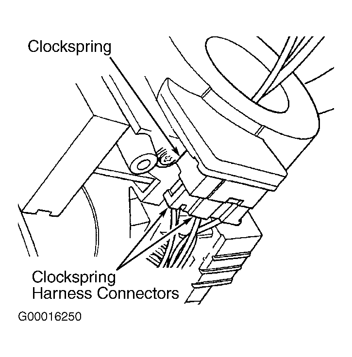 Courtesy of DAIMLERCHRYSLER CORPORATION
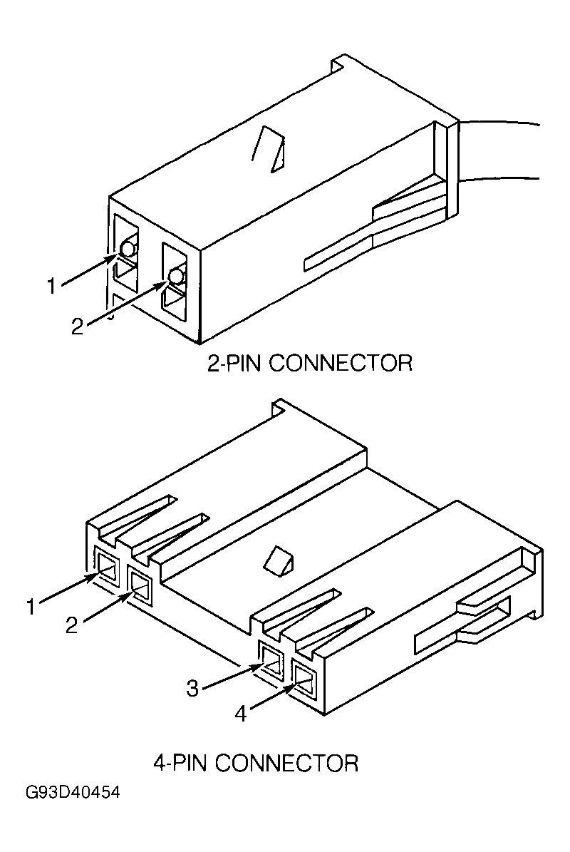 Courtesy of DAIMLERCHRYSLER CORPORATION