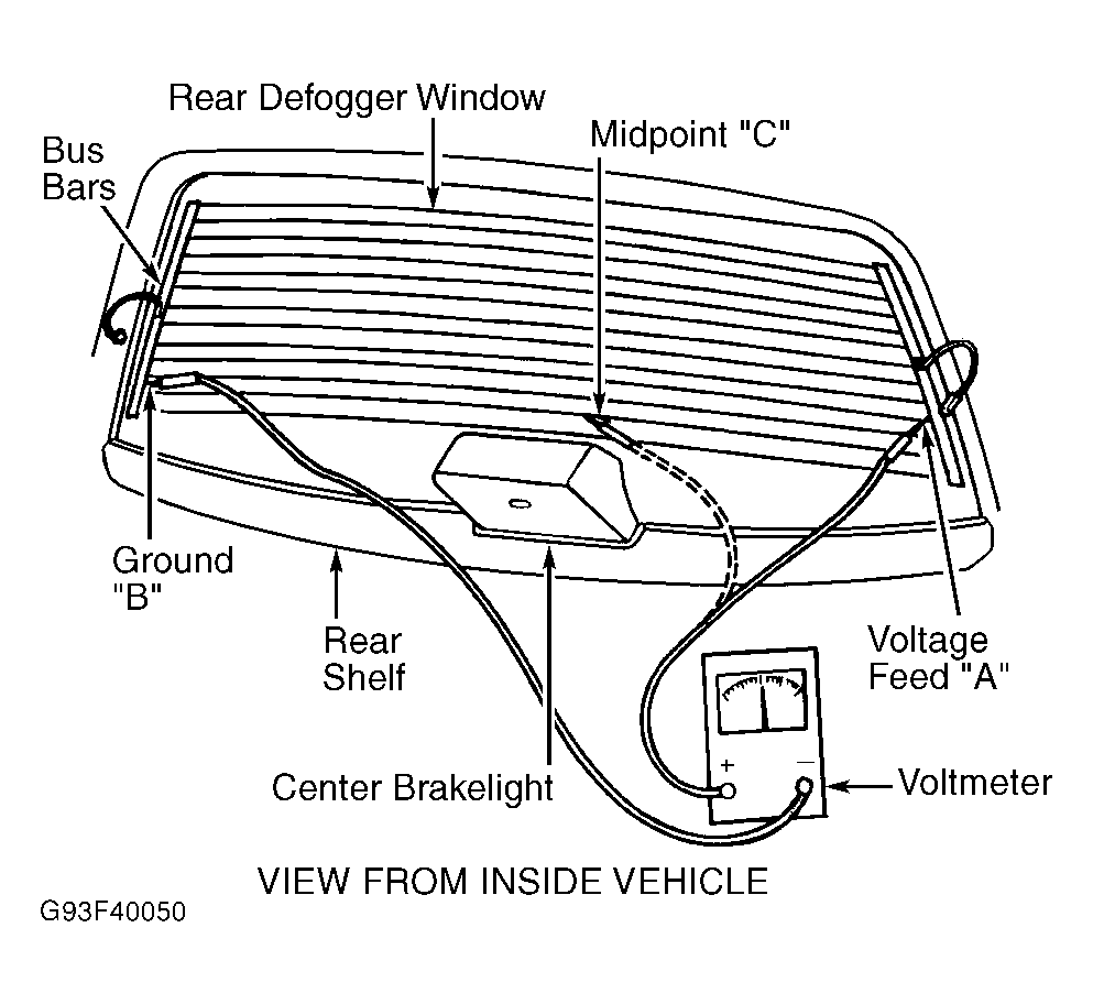
Grid Filament Test
- Turn engine off. Using a voltmeter with negative lead connected to ground, connect positive lead to bus bar ground "B" terminal. See Fig 1
. Turn ignition and control switch to ON position. If voltage is less than one volt, go to next step. If voltage is one volt or more, go to step 3
.
- Connect negative lead of voltmeter to bus bar ground "B" terminal. Connect positive lead of voltmeter to bus bar voltage feed "A" terminal. Voltmeter reading should be 10-14 volts. A lower voltage reading indicates a poor ground connection or an open grid filament. Go to next step.
- Connect negative lead of voltmeter to ground "B" terminal and touch each grid line at midpoint "C" with positive lead. A reading of about 6 volts indicates line is good. A reading of zero volts indicates a break in line between midpoint "C" and voltage feed "A" terminal. A reading of 10-14 volts indicates a break in line between midpoint "C" and ground "B" terminal. Go to next step.
- Move probe toward voltage feed "A" terminal or ground "B" terminal. Voltage will change when break is crossed. Repair grid line(s) as necessary. See GRID FILAMENT REPAIR
under ON-VEHICLE SERVICE.
 Courtesy of DAIMLERCHRYSLER CORP.