DTC P0703: Brake Switch Sense Circuit: Testing
- Turn ignition off. Connect scan tool to DLC. Turn ignition on. Using scan tool, read DTCs. If GLOBAL GOOD TRIP is displayed and is equal to zero, go to next step. If GLOBAL GOOD TRIP is not displayed or is more than zero, go to step 8
.
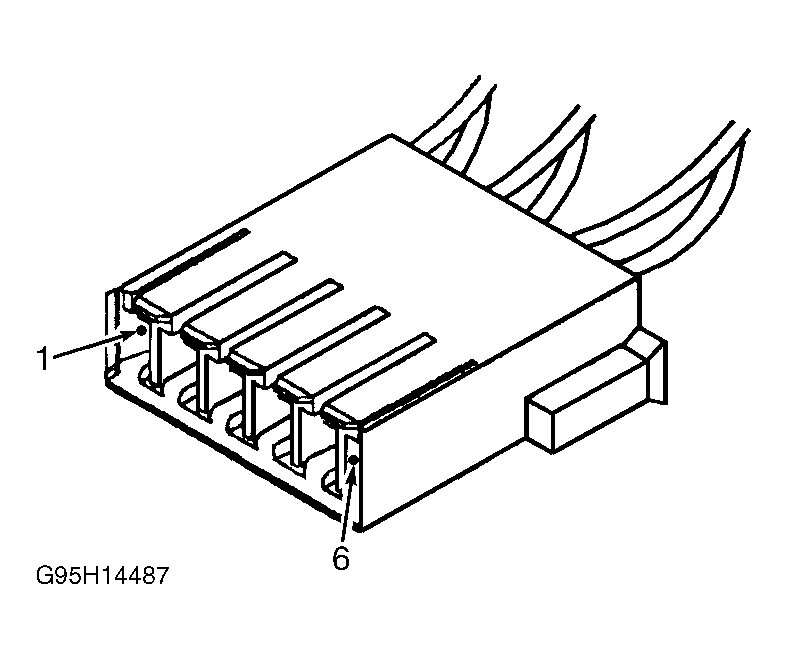
- Turn ignition off. Disconnect brake switch connector. Using a 12-volt test light connected to ground, probe brake switch connector terminal No. 6, fused B+ circuit (Pink/Dark Blue wire). See Fig 1
. If test light illuminates brightly, leave brake switch connector disconnected and go to next step. If test light does not illuminate brightly, repair Pink/Dark Blue wire as necessary. Perform POWERTRAIN VERIFICATION TEST VER-4
under VERIFICATION TESTS.
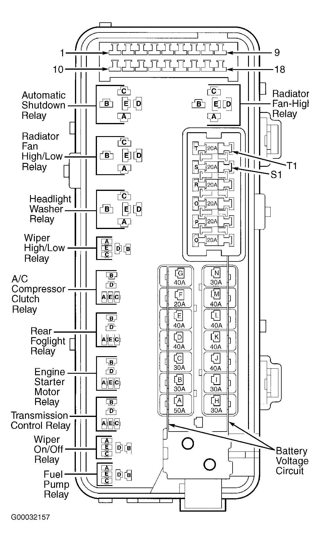
- Ensure ignition is off. Disconnect PCM connectors. Remove Automatic Shutdown (ASD) relay from Power Distribution Center (PDC). See Fig 2
. Connect a jumper wire between ASD relay connector terminal "A" or "B", fused B+ circuits (Red White wires) and ASD relay connector terminal "D", ASD relay output circuit (Dark Green/Orange wire). Turn ignition on. Measure voltage on brake switch connector terminal No. 1, brake switch sense circuit (White/Pink wire). If voltage is more than one volt, repair short to voltage in White/Pink wire. Perform POWERTRAIN VERIFICATION TEST VER-4
under VERIFICATION TESTS. If voltage is one volt or less, leave brake switch and PCM connectors disconnected and go to next step.
- Turn ignition off. Measure resistance between ground and brake switch connector terminal No. 1, brake switch sense circuit (White/Pink wire). If resistance is less than 5 ohms, repair short to ground in White/Pink wire. Perform POWERTRAIN VERIFICATION TEST VER-4
under VERIFICATION TESTS. If resistance is 5 ohms or more, leave brake switch and PCM connectors disconnected and go to next step.
- Measure resistance of brake switch sense circuit (White/Pink wire) between brake switch connector terminal No. 1 and PCM connector C2 terminal No. 62. See Figure
. If resistance is less than 5 ohms, leave brake switch connector disconnected and go to next step. If resistance is 5 ohms or more, repair open in White/Pink wire. Perform POWERTRAIN VERIFICATION TEST VER-4
under VERIFICATION TESTS.
- Measure resistance between ground and brake switch connector terminal No. 2, ground circuit (Black/Light Green wire). If resistance is less than 5 ohms, leave brake switch connector disconnected and go to next step. If resistance is 5 ohms or more, repair open in Black/Light Green wire. Perform POWERTRAIN VERIFICATION TEST VER-4
under VERIFICATION TESTS.
- Measure resistance between brake switch terminals No. 1 and 2. See Figure
. Apply and release brake pedal while monitoring resistance reading. With brake pedal released (brake switch plunger pushed in) resistance should be less than 5 ohms. With brake pedal applied (brake switch plunger extended) resistance should more than 5 ohms. If resistance is as specified, replace PCM. See POWERTRAIN CONTROL MODULE
under REMOVAL & INSTALLATION. Perform POWERTRAIN VERIFICATION TEST VER-4
under VERIFICATION TESTS. If resistance is not as specified, replace brake switch. See BRAKE SWITCH
under REMOVAL & INSTALLATION. Perform POWERTRAIN VERIFICATION TEST VER-4
under VERIFICATION TESTS.
- Conditions required to set DTC are not present at this time. Fault may be intermittent. Using scan tool, check freeze frame data to determine conditions when DTC set. Monitor scan tool while wiggling related wiring and connectors. See WIRING DIAGRAMS
. Check related wiring and connectors for poor connections or damage to wiring harness. Repair any problems found as necessary. Perform POWERTRAIN VERIFICATION TEST VER-4
under VERIFICATION TESTS. If no problems are found, check if any Technical Service Bulletins (TSBs) apply to vehicle. If no TSBs apply, test is complete.
 Courtesy of CHRYSLER CORP.
 Courtesy of DAIMLERCHRYSLER CORP.