Door Lock Switch
- Remove door trim panel to access suspect door lock switch. See DOOR TRIM PANEL
under REMOVAL & INSTALLATION. Disconnect door lock switch connector.
- Connect a 12-volt test light between door lock switch connector terminal No. 1, fused B+ circuit (Pink wire) and terminal No. 3, ground circuit (Black wire). See Fig 1
. If test light illuminates brightly, circuits between battery and door lock switch are functional.
- If test light does not illuminate brightly, remove and inspect fuse No. 14 (10-amp) for passenger's door, or fuse No. 19 (10-amp) for driver's door from junction block. See Fig 2
and Fig 3
. If fuse is okay, repair open door lock switch circuit. See WIRING DIAGRAMS
. If fuse is blown, replace fuse and go to next step.
- Operate suspect door lock switch. Remove and inspect fuse No. 14 (10-amp) for passenger's door, or fuse No. 19 (10-amp) for driver's door from junction block. If fuse is blown, repair suspect door lock switch circuit for short to ground. See WIRING DIAGRAMS
. If fuse is not blown, test is complete.
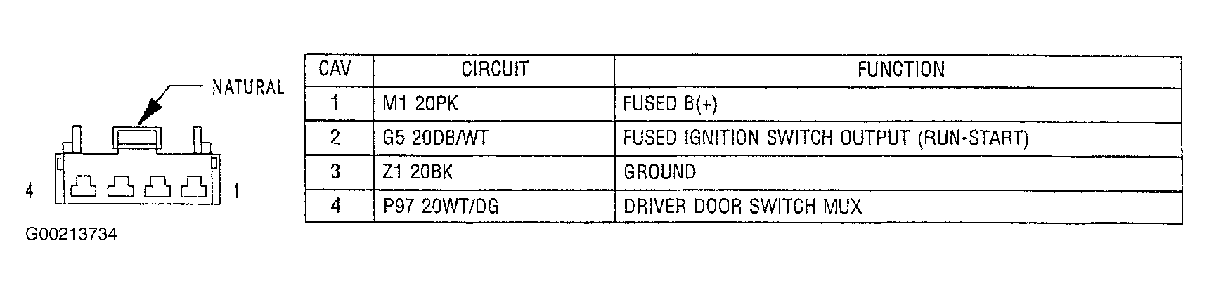 Courtesy of DAIMLERCHRYSLER CORP.
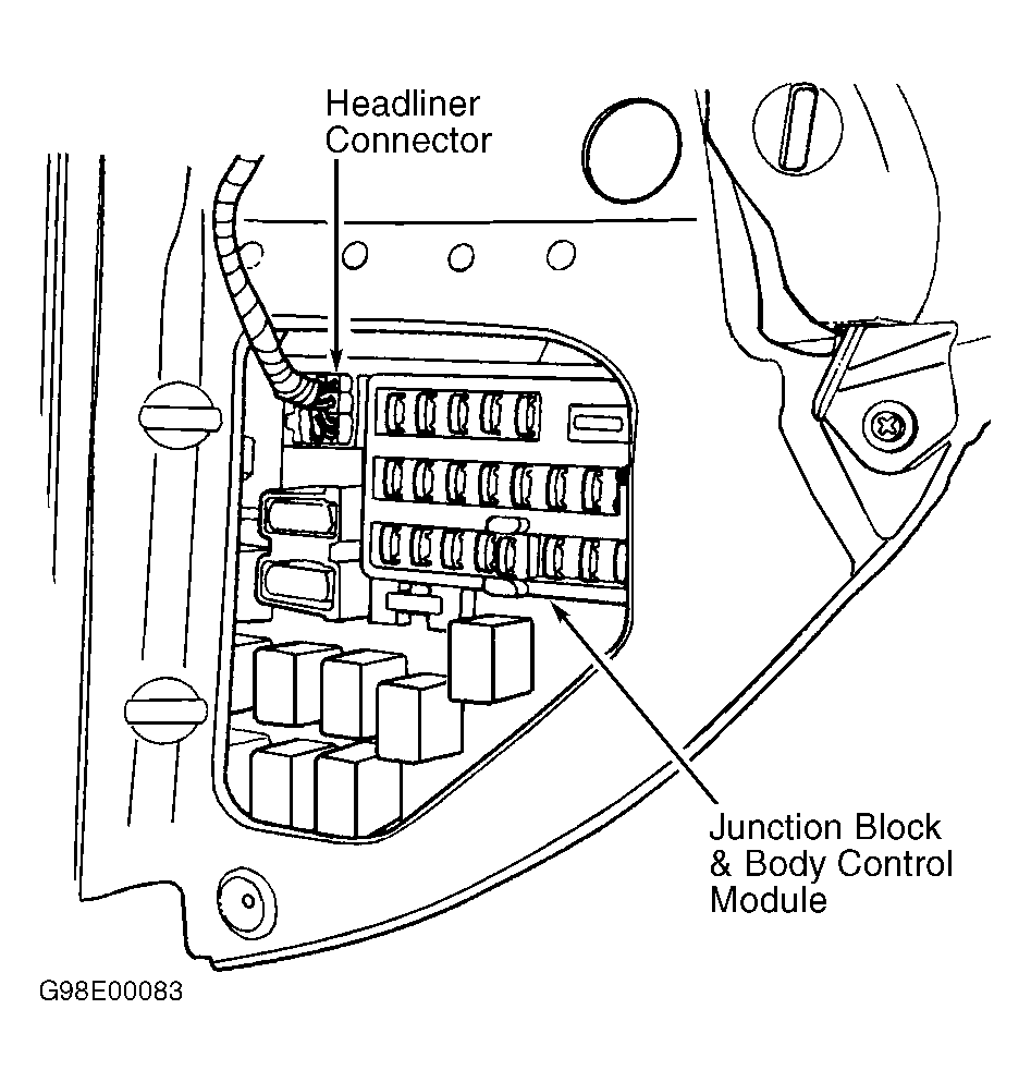 Courtesy of CHRYSLER CORP.
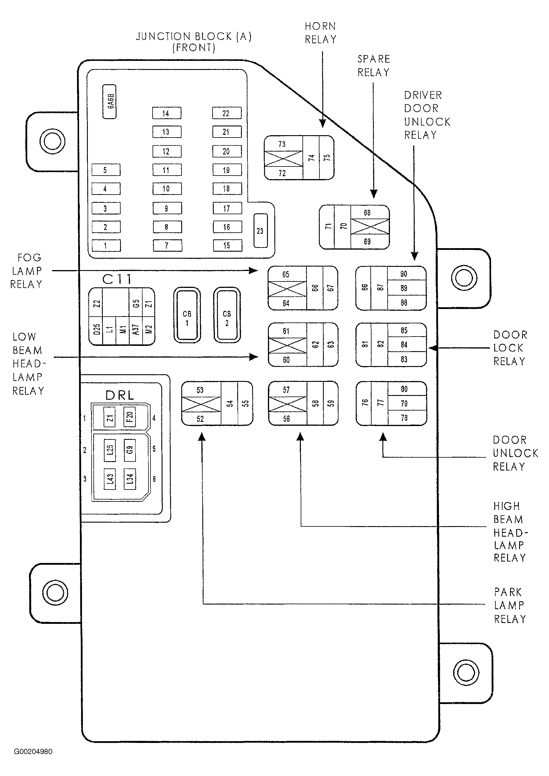 Courtesy of DAIMLERCHRYSLER CORP.