41AE/Te Automatic Transaxle: Removal
- Open hood.
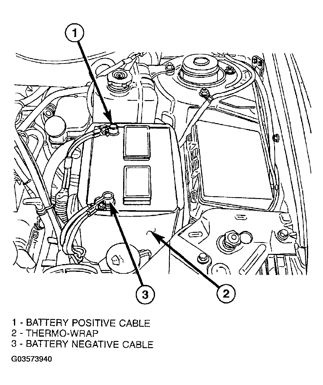
- Disconnect battery cables (Fig 1).
- Remove battery hold-down clamp.
- Remove battery (Fig 1).
 Courtesy of DAIMLERCHRYSLER CORP.
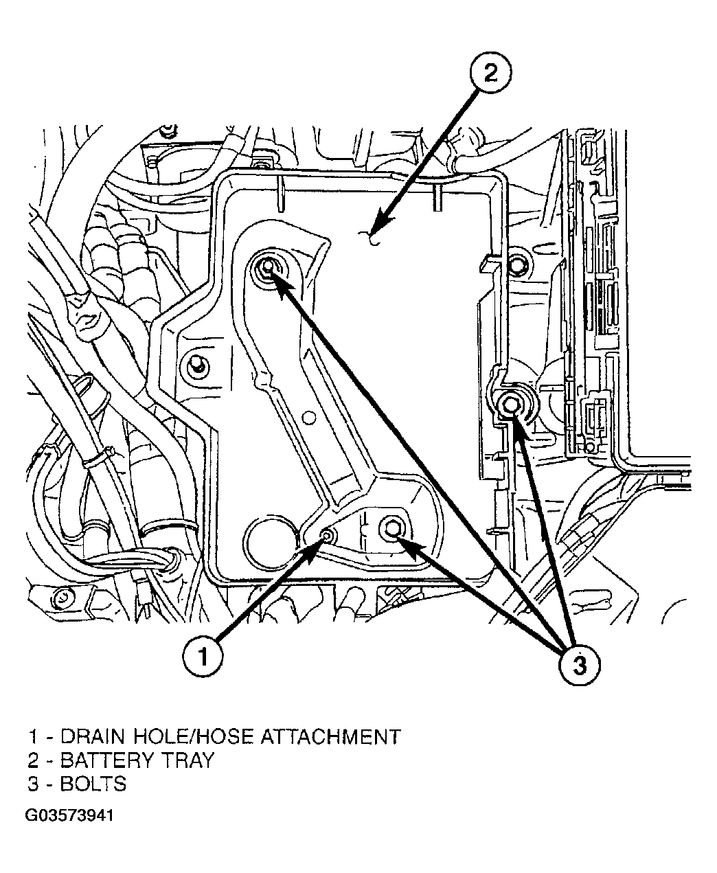
- Remove battery tray (Fig 2). Disconnect battery temperature sensor.
 Courtesy of DAIMLERCHRYSLER CORP.
- Disconnect gearshift cable from transaxle manual valve lever.
- Release and slide transaxle oil cooler hose clamps off of hose/fitting connection. Using suitable cutting tool, cut oil cooler hoses off flush at fittings. A service splice kit will be installed upon assembly. Cap off hoses and fittings to prevent debris intrusion.
- Remove ground cable/bolt from top of transaxle case.
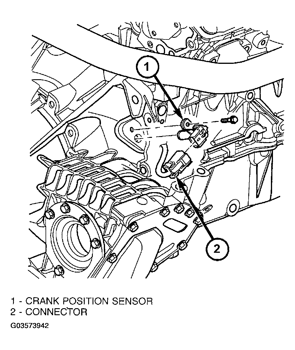
- Disconnect and remove crankshaft position sensor (Fig 3).
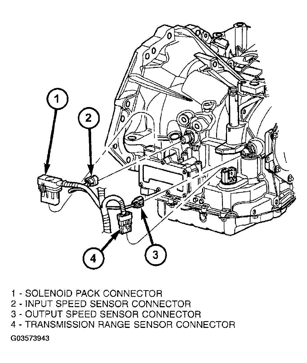
- Disconnect input speed sensor connector (Fig 4).
- Disconnect output speed sensor connector (Fig 4).
- Disconnect transaxle range sensor connector (Fig 4).
- Disconnect solenoid/pressure switch assembly connector (Fig 4).
 Courtesy of DAIMLERCHRYSLER CORP.
 Courtesy of DAIMLERCHRYSLER CORP.
- Release transaxle harness from retainers and position out of way (Fig 5).
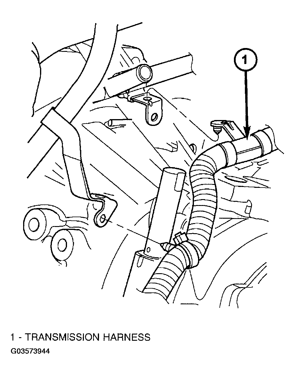 Courtesy of DAIMLERCHRYSLER CORP.
- Remove coolant bypass tube-to-engine and transaxle fasteners.
- Disconnect front brake lines from the hydraulic control unit (Fig 6). Position out of way for removal clearance.
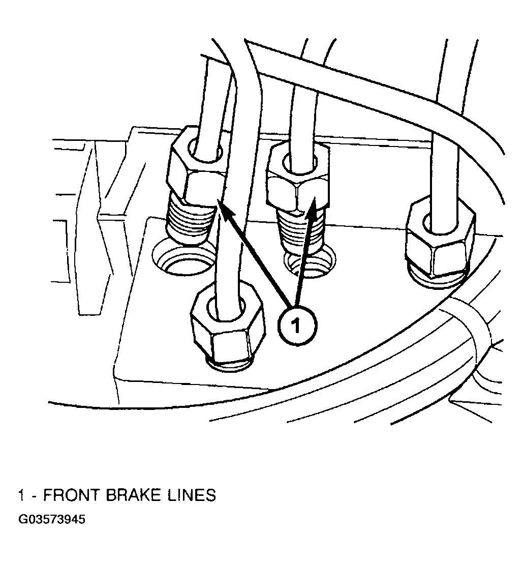 Courtesy of DAIMLERCHRYSLER CORP.
- Remove intermediate shaft extension from steering gear (Fig 8). Remove roll pin using Tool 6831A (Fig 7). Slide shaft extension off of gear.
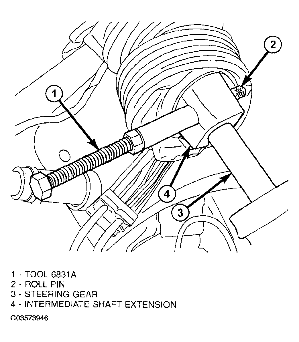 Courtesy of DAIMLERCHRYSLER CORP.
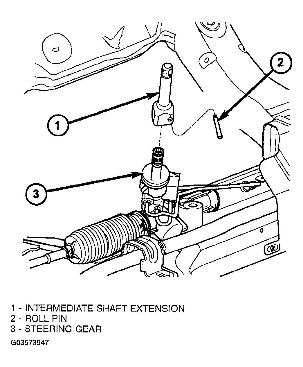 Courtesy of DAIMLERCHRYSLER CORP.
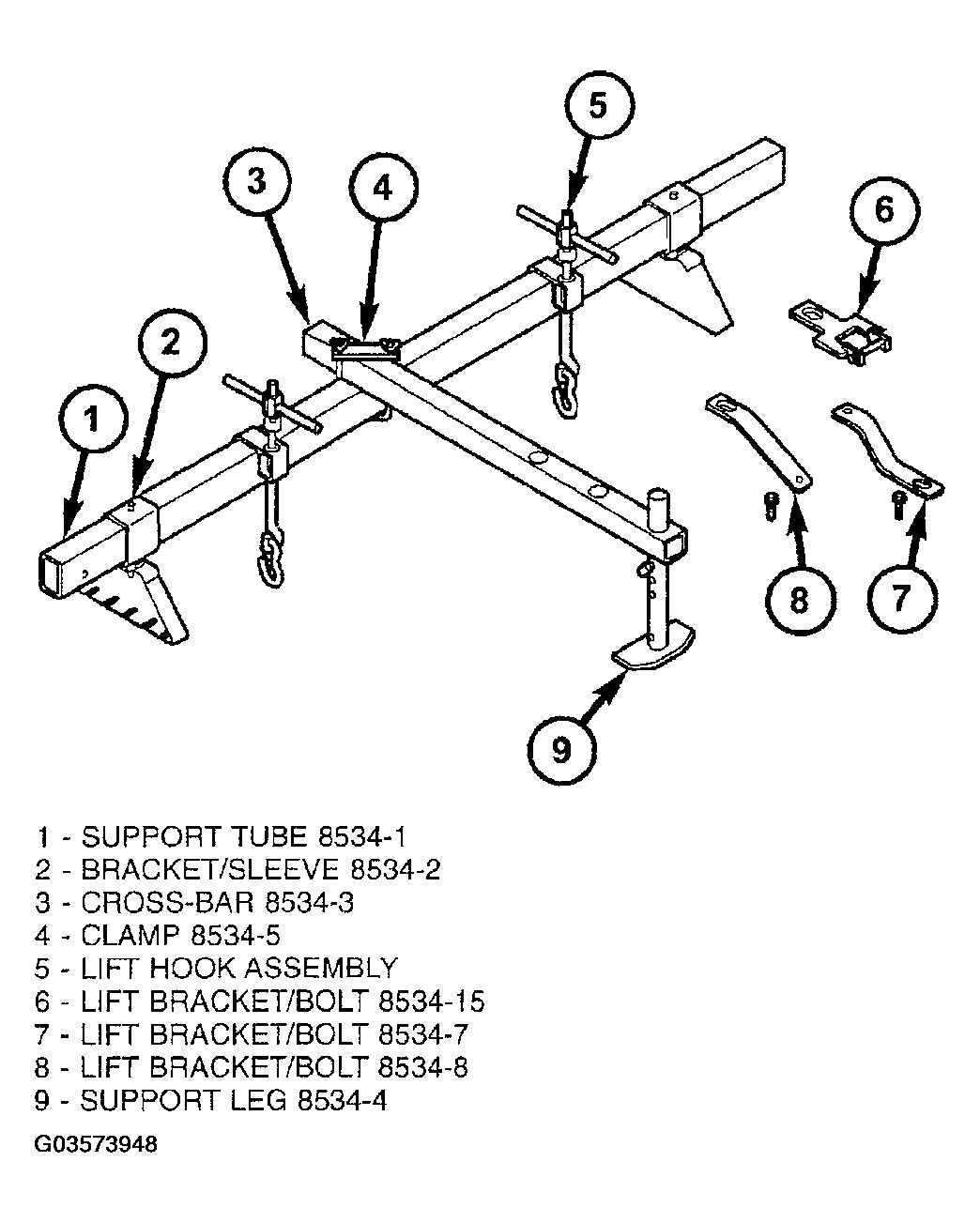
- Install overhead powertrain support fixture (Tool 8534B and adapter kit 8534-12) (Fig 9):
 Courtesy of DAIMLERCHRYSLER CORP.
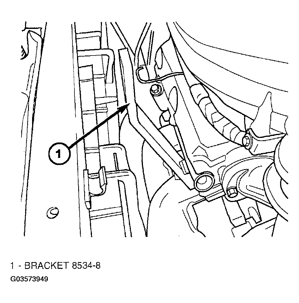
- Remove engine oil dipstick tube-to-cylinder head fastener (Fig 10). Install lift/support bracket 8534-8 and secure with dipstick tube bolt.
 Courtesy of DAIMLERCHRYSLER CORP.
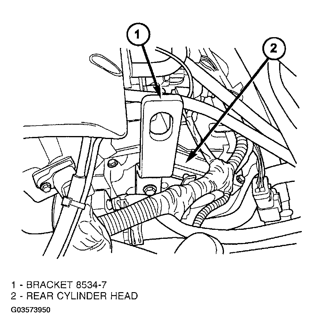
- Disconnect coolant temperature sensor (at thermostat housing). Remove engine harness-to-cylinder head bolt. Position harness out of the way. Install and secure lift/support bracket and bolt 8534-7 as shown in (Fig 11).
 Courtesy of DAIMLERCHRYSLER CORP.
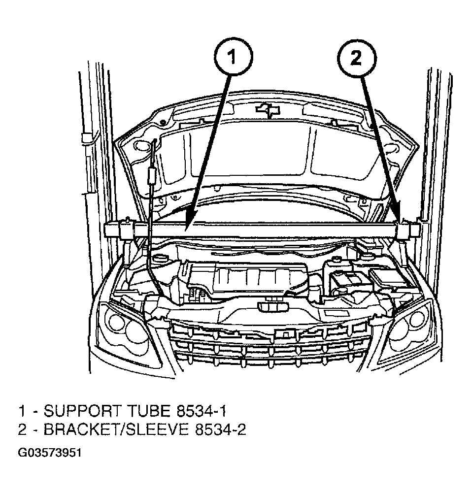
- Assemble 8534-2 mounting bracket/sleeve assemblies to support tube 8534-1 and install to vehicle, allowing brackets to rest on inner fender ledges (Fig 12).
 Courtesy of DAIMLERCHRYSLER CORP.
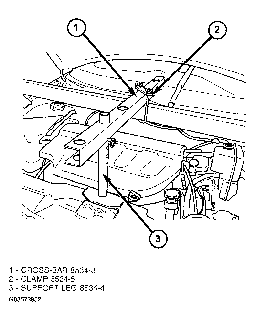
- Assemble cross-bar 8534-3, clamp 8534-5 and support leg 8534-4 to support tube, allowing support leg to rest on radiator upper support (Fig 13).
 Courtesy of DAIMLERCHRYSLER CORP.
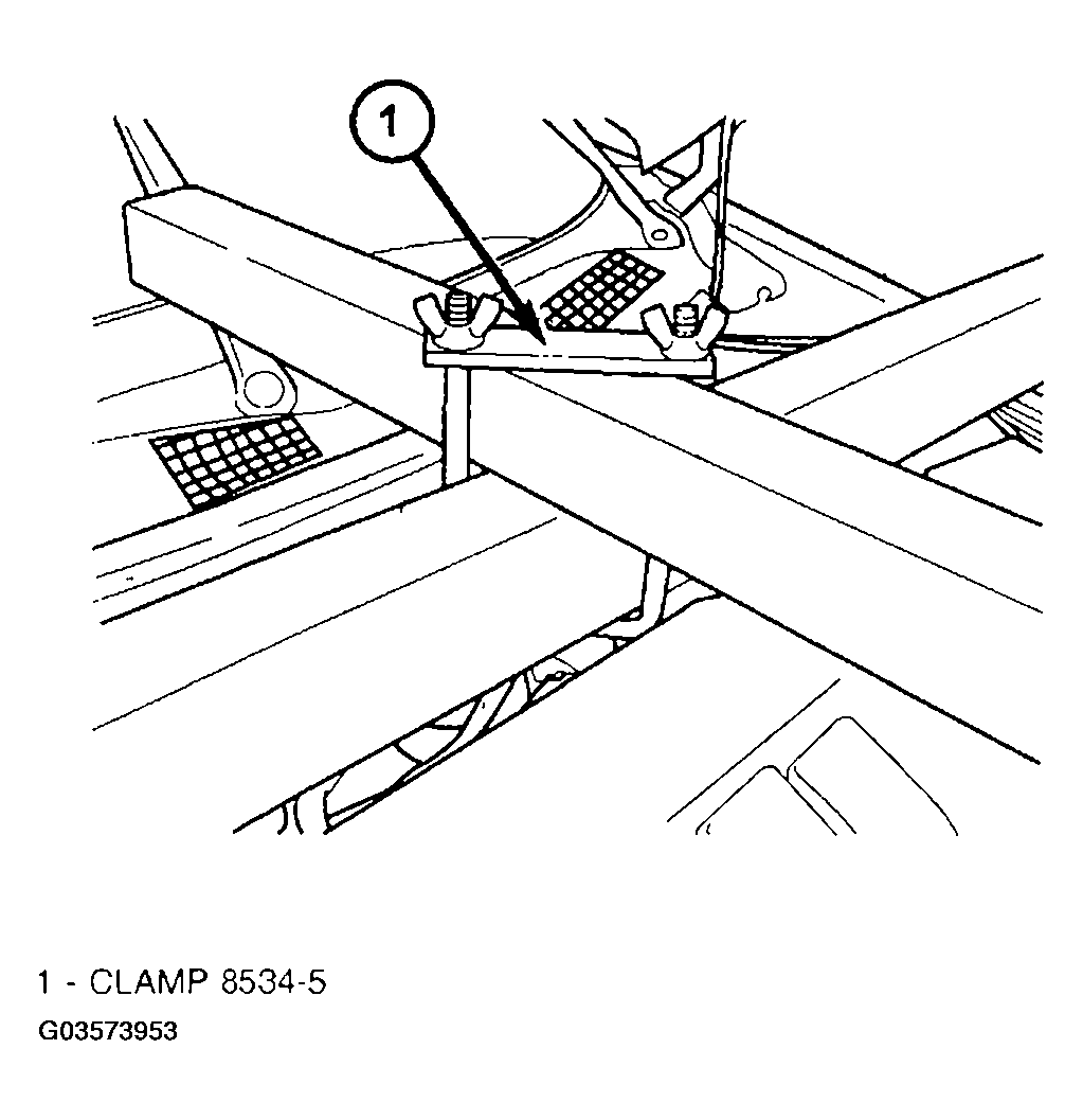
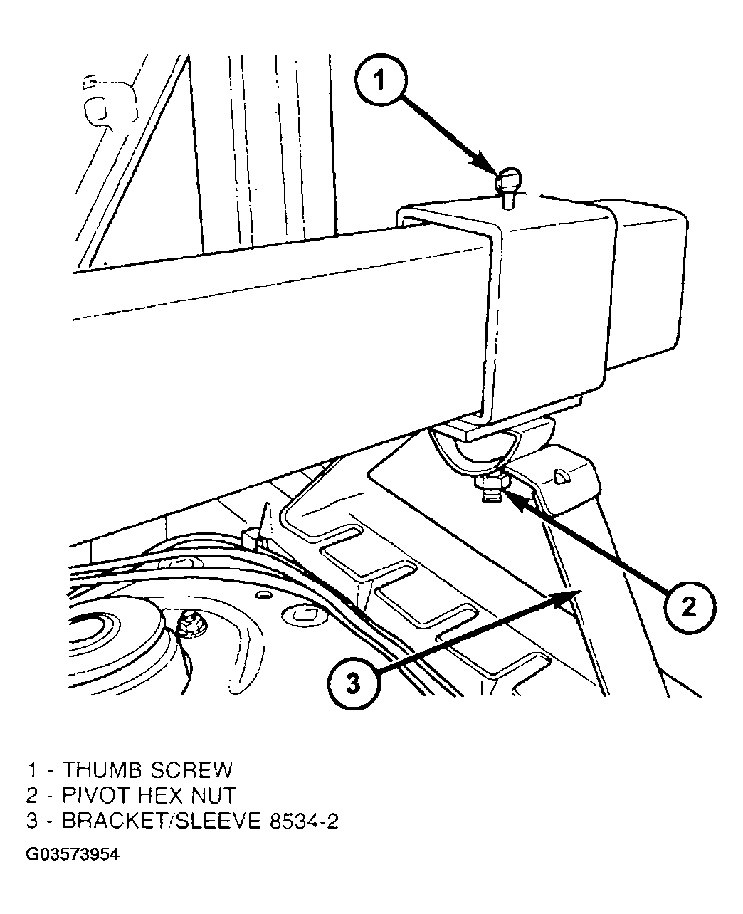
- Tighten cross-bar-to-support tube clamp 8534-5 (Fig 14), as well as mounting bracket/sleeve 8534-2 thumb screw and hex nut to secure fixture (Fig 15).
 Courtesy of DAIMLERCHRYSLER CORP.
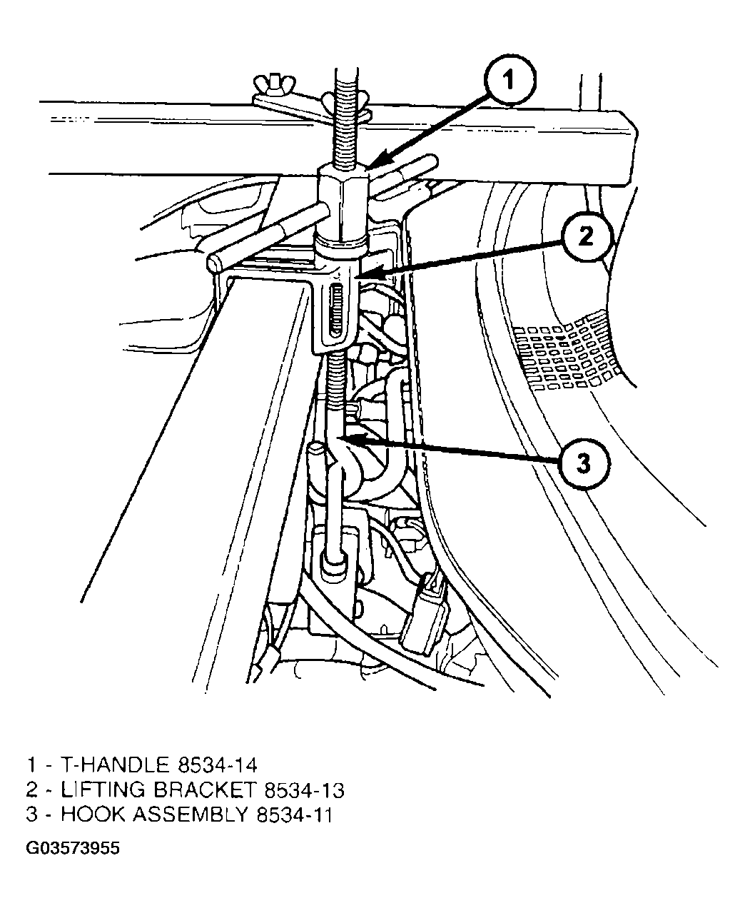
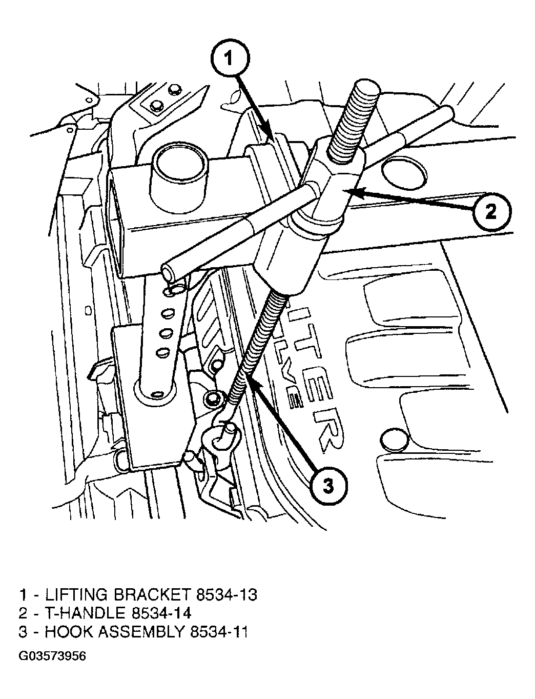
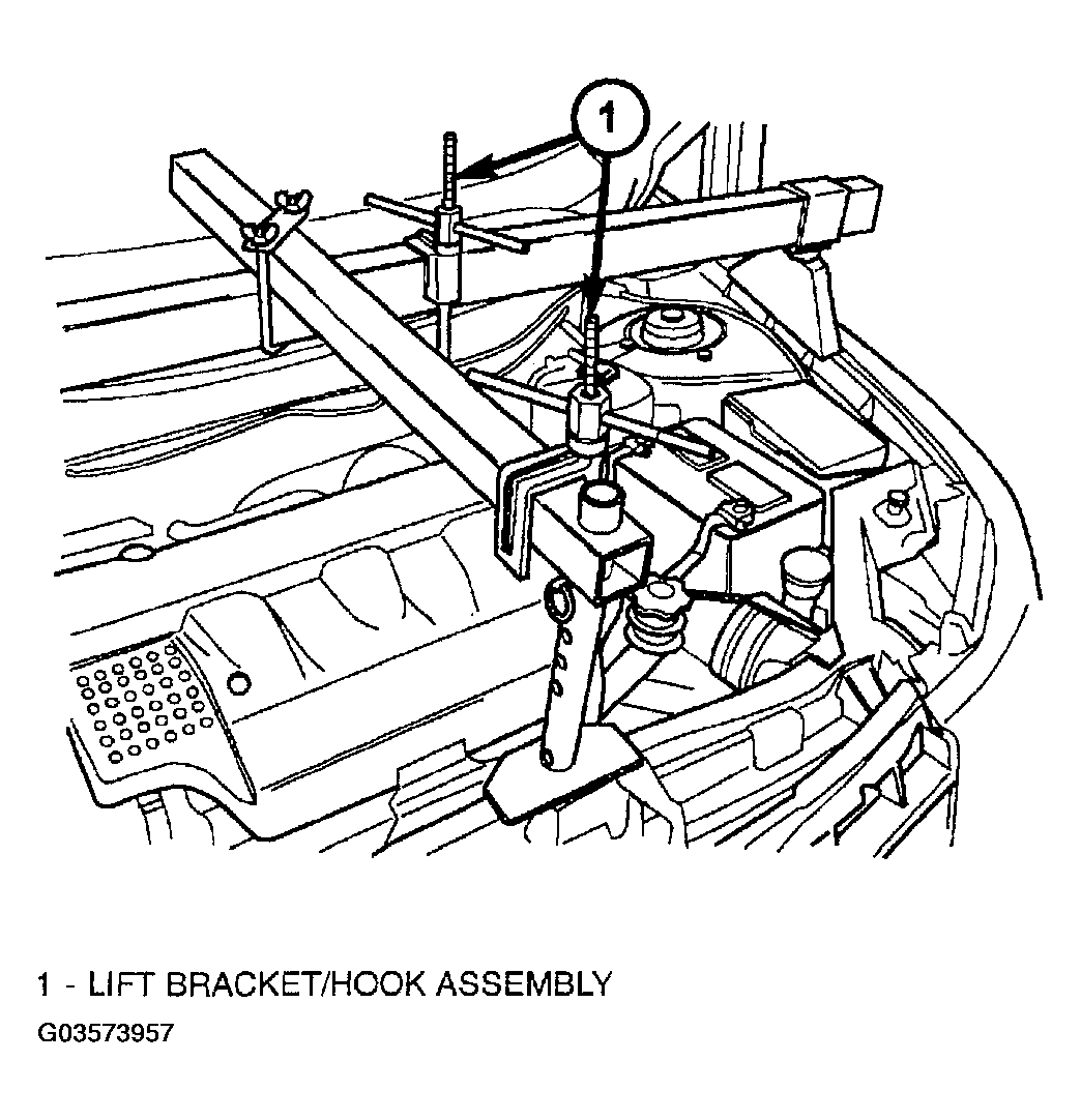
- Install lift bracket/hook assemblies as shown in (Fig 15) (Fig 16) (Fig 17) (Fig 18). Tighten t-handles just enough to build tension between the fixture and drivetrain.
 Courtesy of DAIMLERCHRYSLER CORP.
 Courtesy of DAIMLERCHRYSLER CORP.
- Raise vehicle on hoist.
- Remove both front tire/wheel assemblies.
 Courtesy of DAIMLERCHRYSLER CORP.
 Courtesy of DAIMLERCHRYSLER CORP.
- Disconnect ABS sensor connector. Remove ABS sensor brackets from struts.
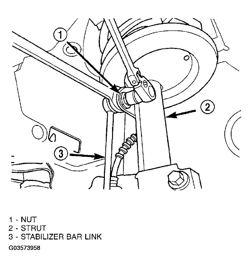
- Disconnect sway bar links from struts (Fig 19).
 Courtesy of DAIMLERCHRYSLER CORP.
- Remove front halfshaft assemblies.
- Remove engine front and rear mount-to-cradle nuts.
- Disconnect brake hydraulic line and brackets from frame rails.
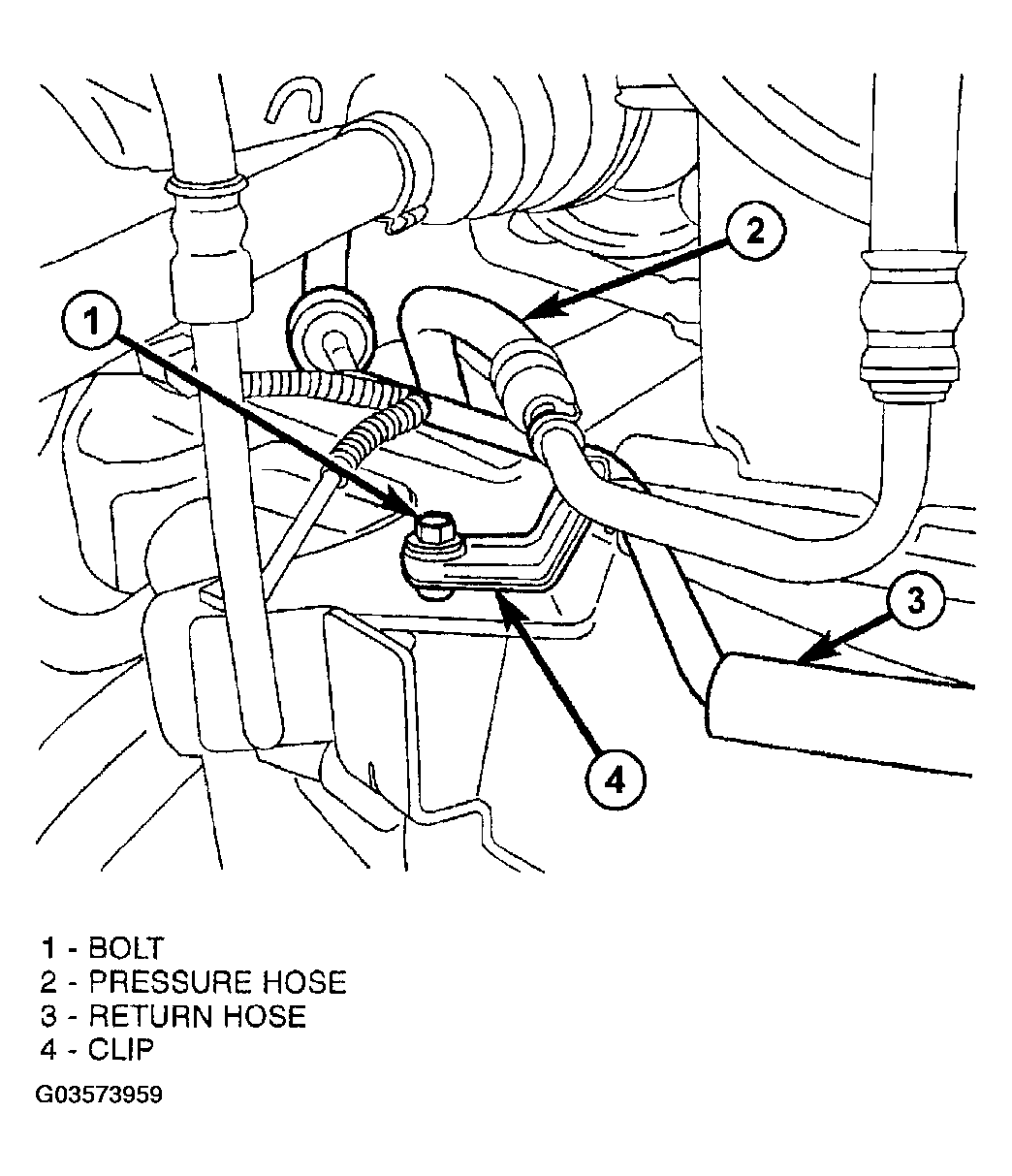
- Disconnect power steering hydraulic line bracket at cradle on passenger side (Fig 20).
 Courtesy of DAIMLERCHRYSLER CORP.
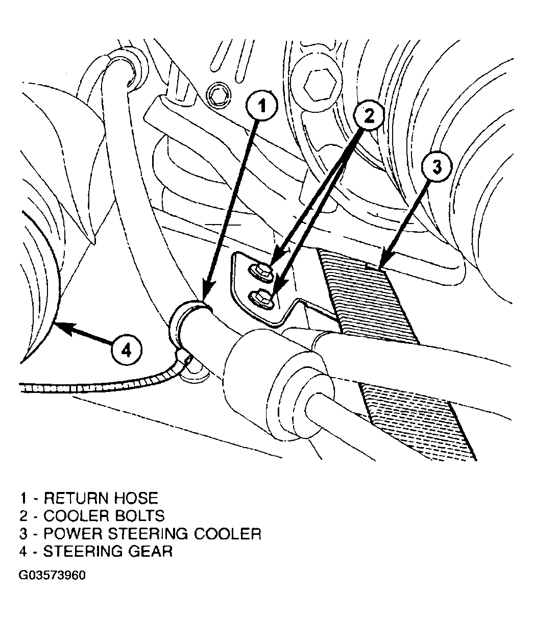
- Disconnect power steering oil cooler from cradle (Fig 21).
 Courtesy of DAIMLERCHRYSLER CORP.
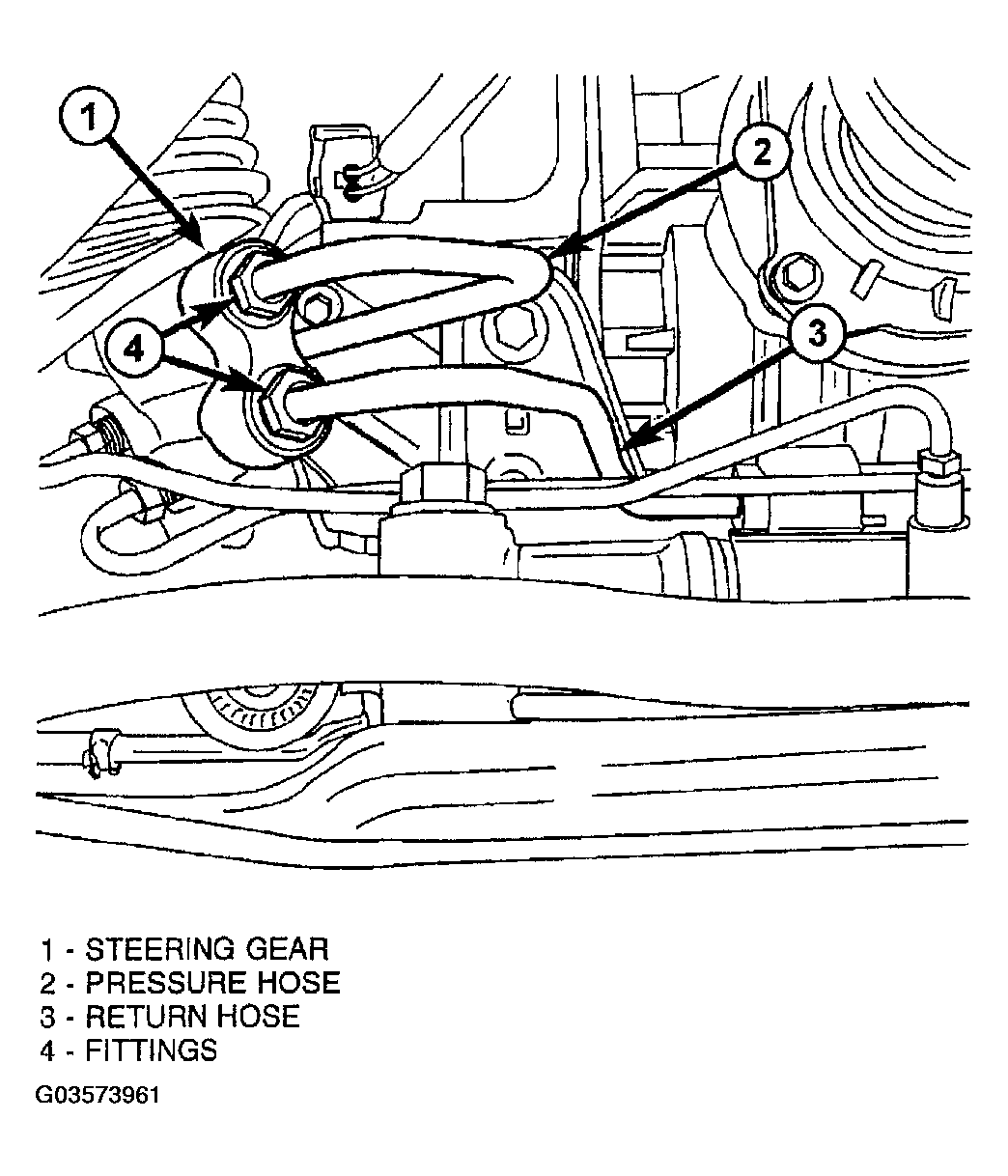
- Disconnect power steering pressure and return lines from steering gear (Fig 22). Cap lines to prevent debris intrusion and tie out of way.
 Courtesy of DAIMLERCHRYSLER CORP.
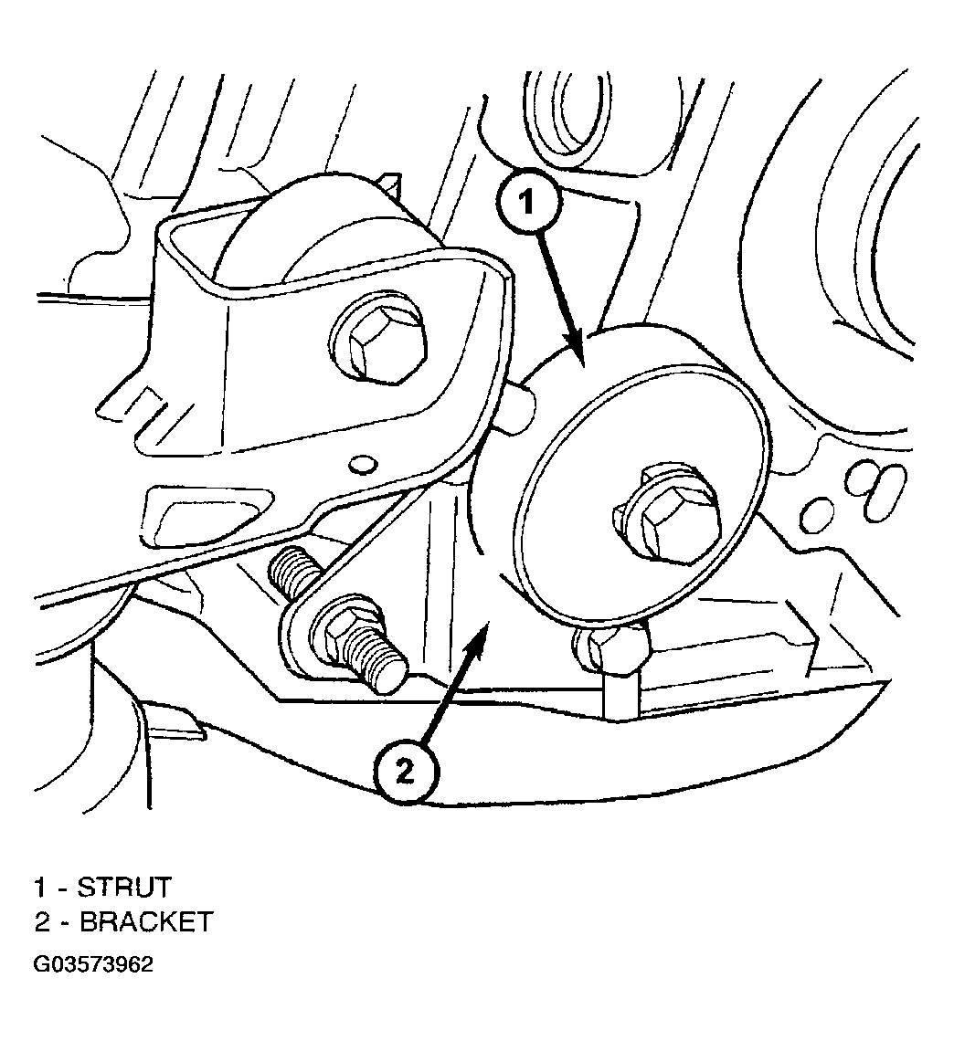
- Remove the transmission-to-cradle torque strut (Fig 23).
 Courtesy of DAIMLERCHRYSLER CORP.
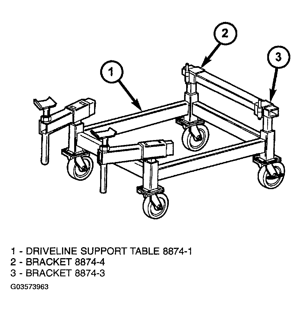
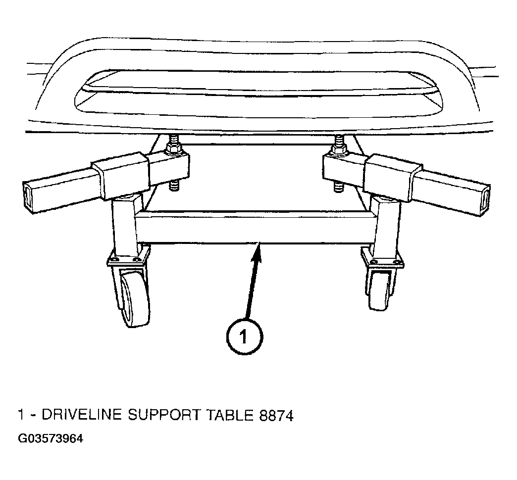
- Set Driveline Support Table, Tool 8874 into position (Fig 24) (Fig 25).
 Courtesy of DAIMLERCHRYSLER CORP.
 Courtesy of DAIMLERCHRYSLER CORP.
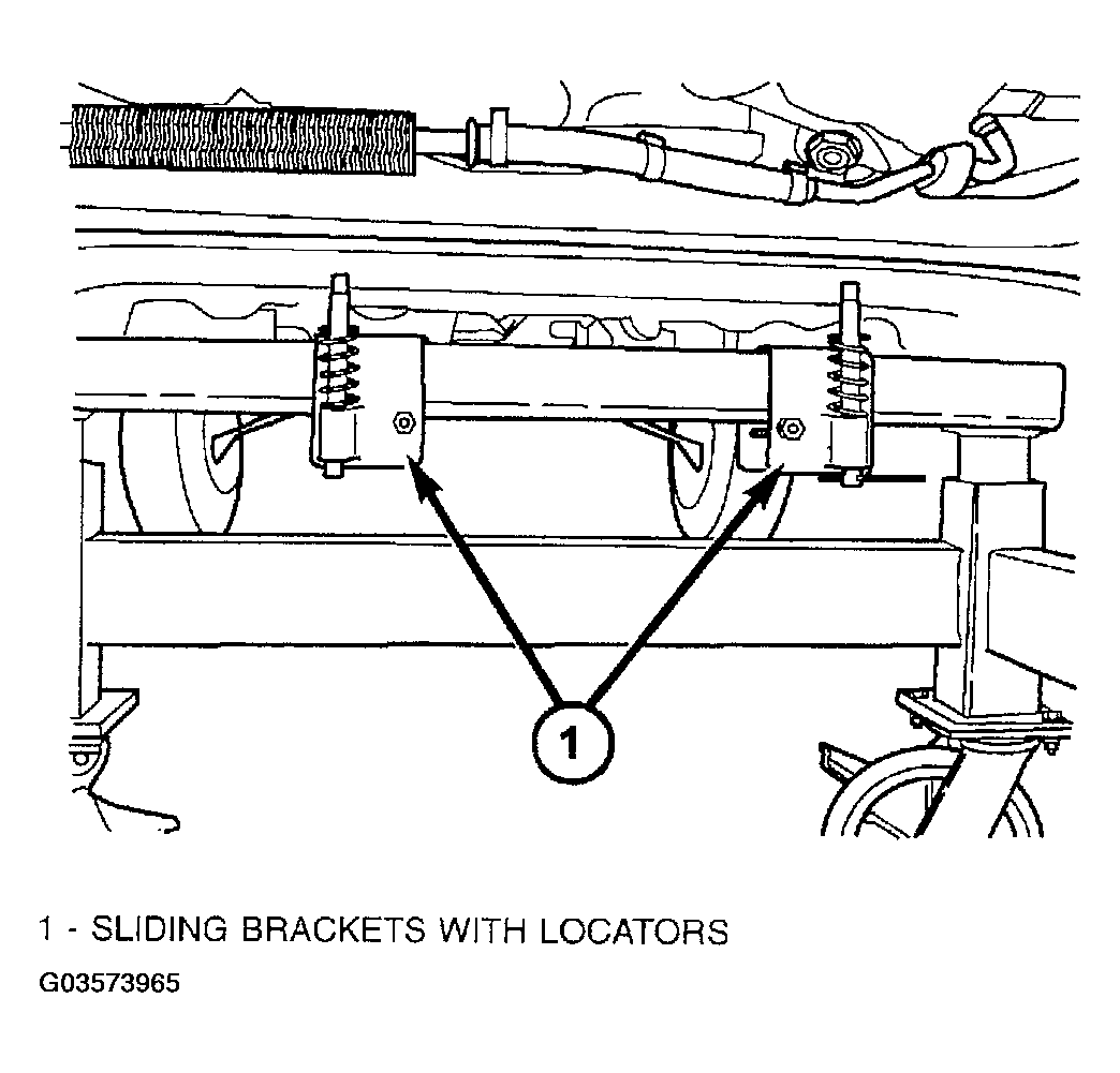
- Lower vehicle until cradle and fixture engage as shown in (Fig 26).
 Courtesy of DAIMLERCHRYSLER CORP.
- Scribe alignment marks to reference the cradle to the body for installation. Remove four (4) cradle-to-body bolts.
- Slowly raise vehicle on hoist to separate cradle from vehicle. Verify that overhead fixture is secure to inner fenders and radiator upper support
. Have helper guide brake and power steering hydraulic lines through, as they will remain attached to cradle assembly.
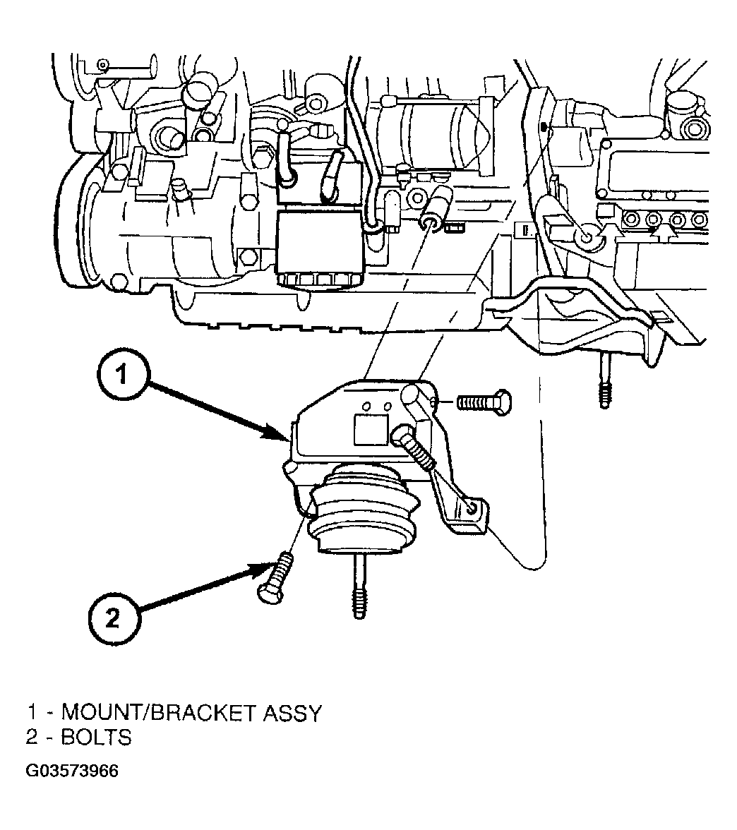
- Remove engine front mount/bracket (Fig 27).
 Courtesy of DAIMLERCHRYSLER CORP.
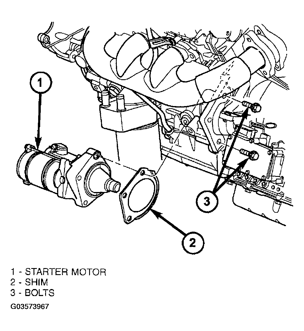
- Disconnect starter motor electrical connectors (Fig 28). Remove starter motor and shim.
 Courtesy of DAIMLERCHRYSLER CORP.
- AWD Models:
- Remove propeller shaft assembly. (Refer to PROPELLER SHAFT (AWD)
).
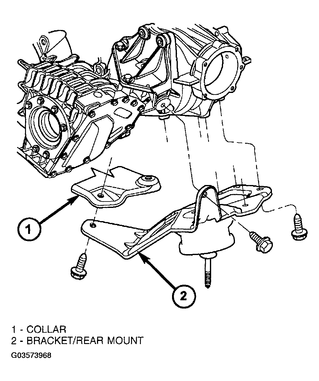
- Remove PTU/rear mount bracket (Fig 29).
 Courtesy of DAIMLERCHRYSLER CORP.
- Remove oil pan-to-transaxle collar (Figure).
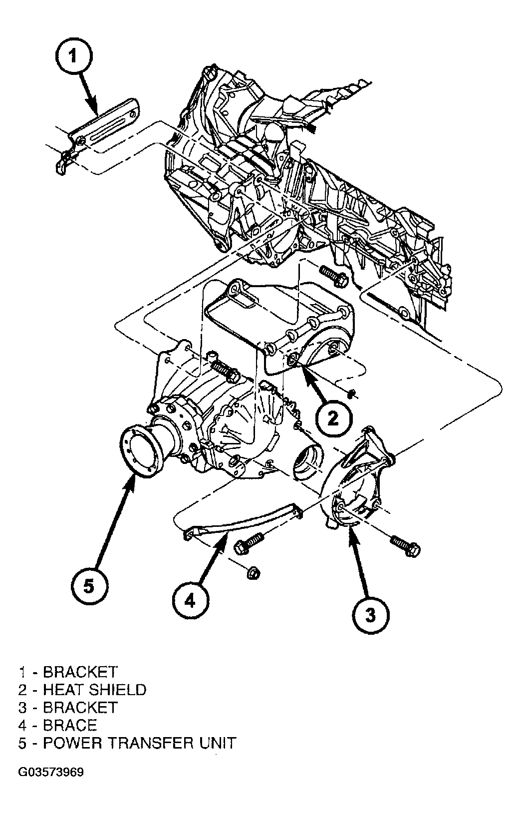
- Remove heat shield (Fig 30).
- Remove PTU-to-transaxle upper bolts (Fig 30).
- Remove PTU-to-bracket lower bolts (Figure).
- Remove PTU from vehicle.
- Remove torque converter dust shield (Figure).
- Remove four (4) torque converter-to-driveplate bolts. Upon removing bolts, a tight-tolerance (slotted) bolt will be encountered. Mark this location (drive-plate and converter) with paint for assembly reference.
- Lower vehicle.
- Remove four (4) transaxle upper bellhousing-to-block bolts.
- Lower engine/transaxle at overhead fixture.
- Raise vehicle.
- Install transmission jack into position. Secure transaxle to jack.
- Remove two (2) transaxle-to-engine lower bolts.
- Lower transaxle from engine compartment.
 Courtesy of DAIMLERCHRYSLER CORP.