- Raise and support vehicle. Refer to STANDARD PROCEDURE
.
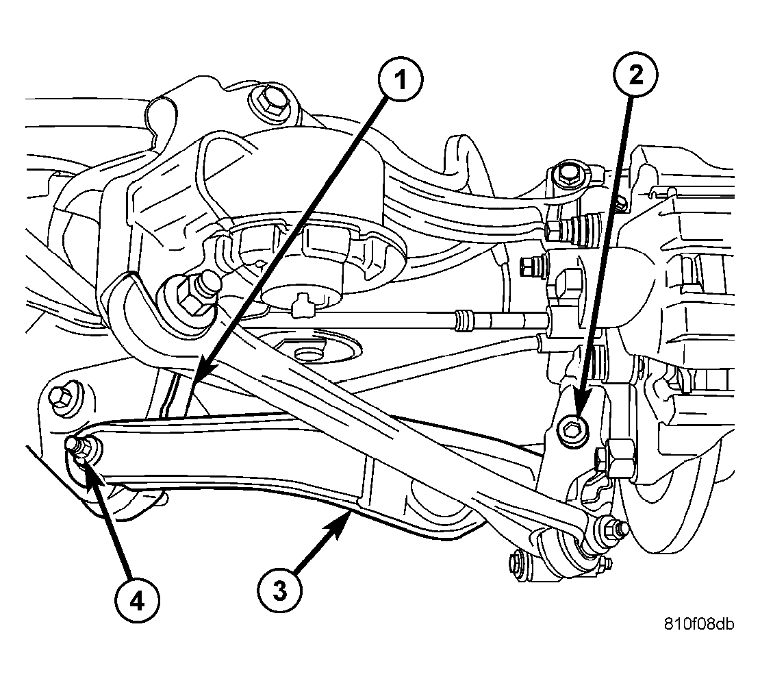
- Access and remove rear spring. See REMOVAL .
 Courtesy of CHRYSLER LLC
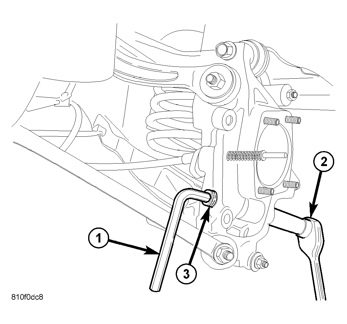
| 1 - HEX WRENCH |
| 2 - RATCHET AND SOCKET ON NUT |
| 3 - BOLT HEAD |
- Remove spring link-to-knuckle nut and bolt (3).
 Courtesy of CHRYSLER LLC
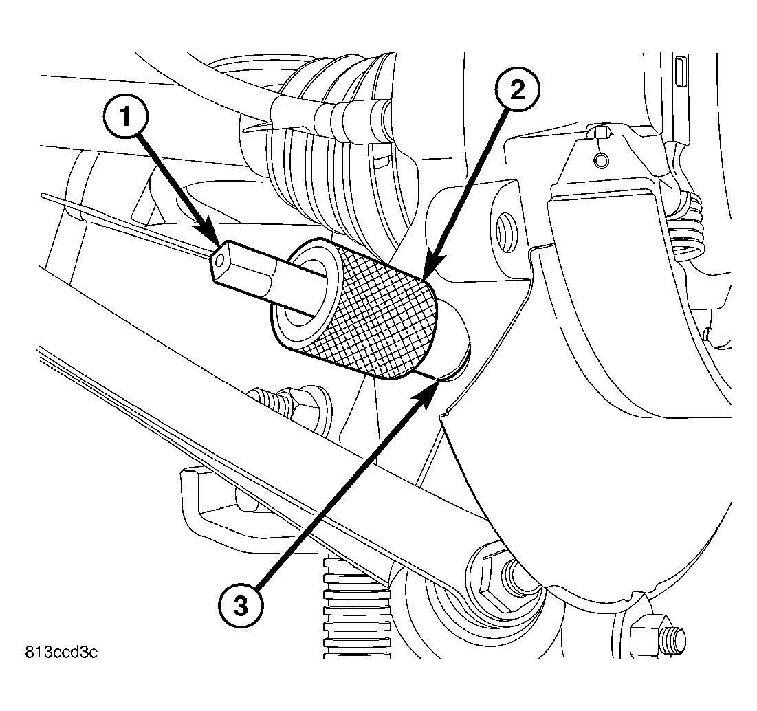
| 1 - TAP 9050A-1 |
| 2 - GUIDE 9050A-2 |
| 3 - SLEEVE IN KNUCKLE |
CAUTION:
It is important to use Guide (2), Special Tool 9050A-2, when tapping sleeve to help keep Tap (1), Special Tool 9050A-1, straight during use or damage to Tap may occur.
- Place Guide 9050A-2 (2) against sleeve (3) in knuckle as shown.
- Insert Tap 9050A-1 (1), on an appropriate handle, through Guide and into sleeve. Cut threads approximately halfway through bushing (or about six complete threads). It is important to back Tap out often and clean out burrs that can build up inside Guide. Keep Tap well lubricated to avoid damaging it.
 Courtesy of CHRYSLER LLC
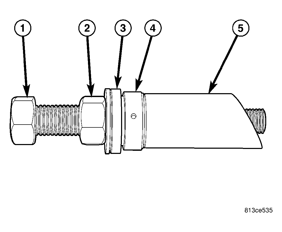
| 1 - BOLT 9050A-3 |
| 2 - NUT |
| 3 - SPHERICAL WASHER |
| 4 - THRUST BUSHING |
| 5 - SLEEVE 9050A-5 |
NOTE:
Prior to using Remover, Special Tool 9050A, lubricate Bolt (1) threads to provide ease of use and promote tool longevity.
- Assemble Remover 9050A as shown.
- BOLT 9050A-3 (1)
- NUT (2)
- SPHERICAL WASHER (3)
- THRUST BUSHING (4)
- SLEEVE 9050A-5 (5)
NOTE:
When installing thrust bearing on Remover, be sure to place hardened side toward nut.
 Courtesy of CHRYSLER LLC
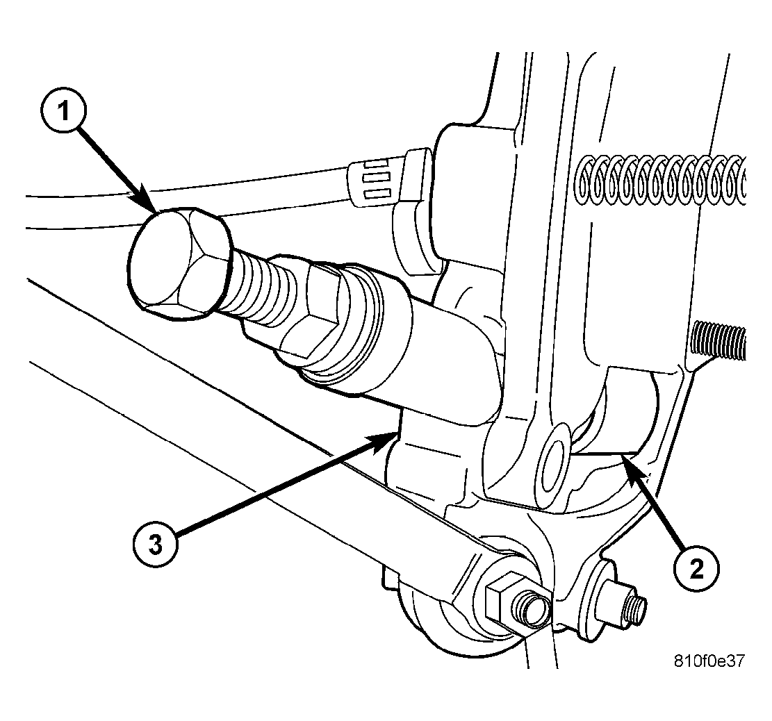
| 1 - REMOVER 9050A |
| 2 - SPRING LINK BALL JOINT |
| 3 - KNUCKLE |
- Remove sleeve retaining spring link ball joint (2) in knuckle (3) as follows:
- Hand thread assembled Remover 9050A (1) into tapped knuckle sleeve until it stops.
- Rotate Nut down, matching Sleeve 9050A-5 angled end with angled face of knuckle.
- Continue to rotate Nut until knuckle sleeve is removed from knuckle. Discard knuckle sleeve; replace it with new upon installation.
 Courtesy of CHRYSLER LLC
| 1 - CROSSMEMBER |
| 2 - MOUNTING BOLT AND NUT |
| 3 - SPRING LINK |
| 4 - MOUNTING BOLT AND NUT |
- Remove bolt and nut (4) fastening spring link to crossmember (1).
- Remove spring link (3).