- If the steering column is being replaced, assemble components on the steering column as necessary before column installation. See ASSEMBLY .
 Courtesy of CHRYSLER LLC
NOTE:
When installing a tilt column, do not release the tilt lever from the locked position until after the column is installed on the instrument panel.
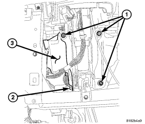
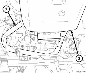
- Install the steering column through the steering column opening.
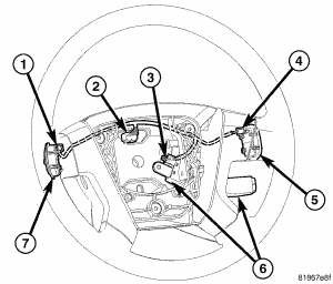
- Raise the column onto the mounting studs and install the three mounting nuts (1) on the studs and the one bolt (2).
 Courtesy of CHRYSLER LLC
NOTE:
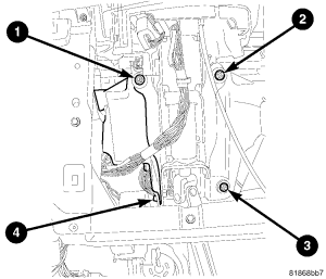
When tightening the fasteners in the following step, make sure there is no gap between the column flange and the instrument panel support at bolt (4).
- Starting with the left upper nut and proceeding in a clockwise tightening sequence ending at the bolt (left lower), tighten all four mounting fasteners to 28 N.m (21 ft. lbs.).
 Courtesy of CHRYSLER LLC
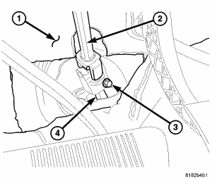
- Verify the front wheels of vehicle are in the STRAIGHT-AHEAD position.
- Collapse the intermediate shaft (2). Center it over the steering gear pinion shaft (4), lining up the ends, then slide the intermediate shaft onto the steering gear pinion shaft. Do not install the intermediate shaft coupling bolt (3) at this time. The bolt can be more easily installed in a later step.
 Courtesy of CHRYSLER LLC
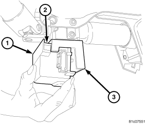
- Connect the wiring harness connectors (2) to the Steering Column Control Module (SCCM) (1).
- Connect any other the wiring harness connectors.
 Courtesy of CHRYSLER LLC
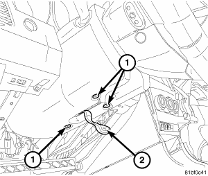
- If equipped, Install the clutch pedal blocker (1) using three mounting screws.
 Courtesy of CHRYSLER LLC
- Push the tilt lever (2) downward (released position).
- Install the lower shroud (2) over the tilt lever and onto the column.
- Install the upper shroud onto the lower shroud, clipping the shrouds to one another.
- Install the three screws (1) attaching the lower shroud to the steering column.
- Position the column tilt (5) at the full-upward position.
- Push the tilt lever upward, locking the column in place.
 Courtesy of CHRYSLER LLC
CAUTION:
When installing the steering wheel, the clockspring must be centered in its travel to avoid overextending the clockspring inner parts, causing the clockspring to become inoperative. If removed and handled properly using the correct procedures, it should be in the "centered" position. If there is any question as to whether the clockspring is in the "centered" position of travel, perform the clockspring centering procedure before proceeding. Refer to STANDARD PROCEDURE
.
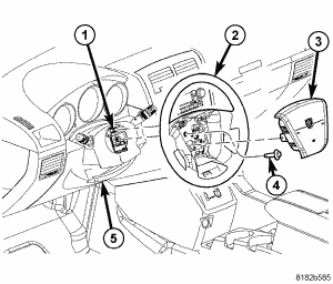
- Install the steering wheel (2) and the retaining bolt (4). Tighten the steering wheel retaining bolt to 50 N.m (37 ft. lbs.). See INSTALLATION .
 Courtesy of CHRYSLER LLC
- Install the speed control switch mounting screw (3).
 Courtesy of CHRYSLER LLC
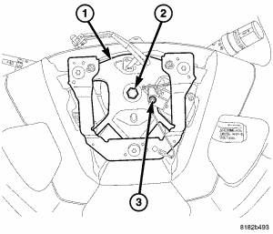
- Connect the wiring connector (2) at the clockspring.
Courtesy of CHRYSLER LLC
- Install the driver airbag (3). Refer to INSTALLATION
.
Courtesy of CHRYSLER LLC
- From center, rotate the steering wheel to the right approximately 90° or until the shaft coupling pinch bolt (3) can be easily installed.
- Install the intermediate shaft coupling bolt (3). Tighten the bolt to 42 N.m (31 ft. lbs.).
- Reposition the floor carpet (1) in place.
- Straighten the steering wheel to STRAIGHT-AHEAD position.
WARNING:
Do not connect the battery ground cable without following the proper procedure as indicated in the following step. Personal injury or death may result if the Airbag System Test is not performed first.
- Reconnect the battery ground terminal following the Airbag System Test found in Restraints article. Refer to DIAGNOSIS AND TESTING
.
 Courtesy of CHRYSLER LLC
- If the steering column being installed requires the installation of a shaft lock module, perform the following:
- If not present, insert the ignition key into the ignition lock cylinder. This will move the shaft lock module locking bolt to the unlocked position. Leave the key in the lock cylinder while the shaft lock module service is being completed.
- Make sure the wiring harness connector is properly connected to the module.
- Align the engagement and slide tabs (2) on the shaft lock module housing (1) with the slots and channels in the mounting bracket (3) on the steering column.
- Carefully slide the module toward the top (steering wheel end) of the column until it is in mounted position and the spring clips on the module have engaged the bracket, locking it in place.
NOTE:
If a NEW module has been installed, a NEW SKREEM (WCM) must also be installed, then a diagnostic scan tool MUST be used to initialize the new module before the vehicle can be operated. Refer to STANDARD PROCEDURE
.
 Courtesy of CHRYSLER LLC
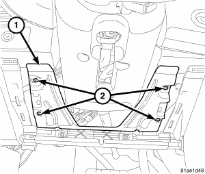
- Install the steering column cover reinforcement (1) using the four mounting screws (2).
- Install the steering column opening cover. Refer to INSTALLATION
.
- Test the operation of the all column mounted components. If applicable, reset the radio and the clock as necessary.
- Road test the vehicle to ensure proper operation of the steering system.