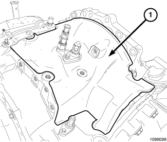
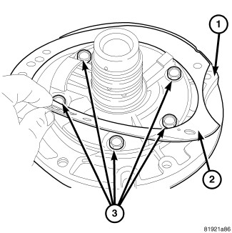
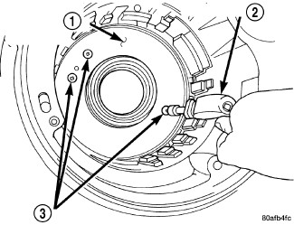
- Remove the speed sensors (1, 2 and 3).
 Courtesy of CHRYSLER LLC
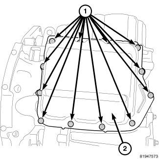
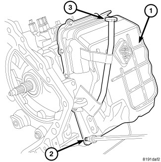
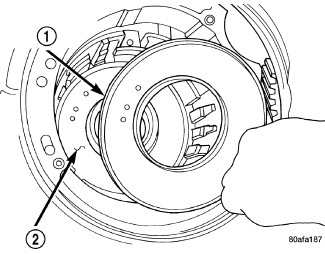
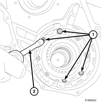
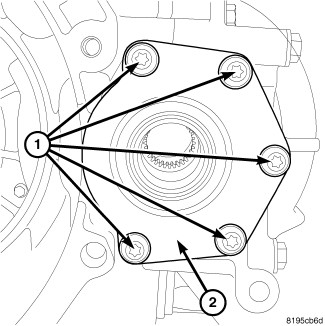
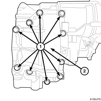
- Remove bolts (1) at the oil filter pan (2).
- Remove the oil filter pan (2).
 Courtesy of CHRYSLER LLC
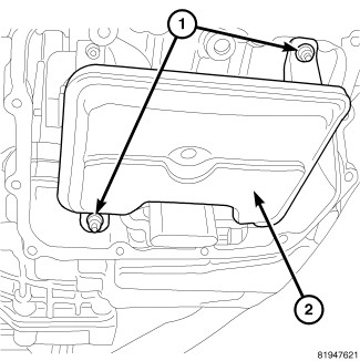
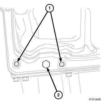
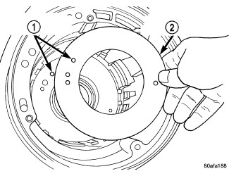
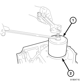
- Remove the bolts (1) at the oil filter (2).
- Remove the oil filter (2).
 Courtesy of CHRYSLER LLC
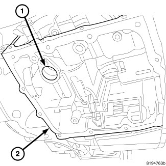
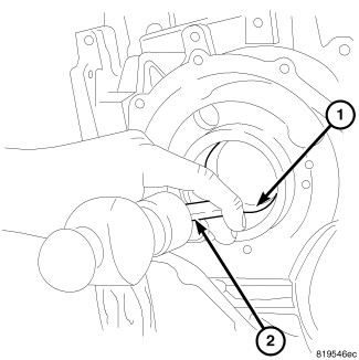
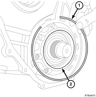
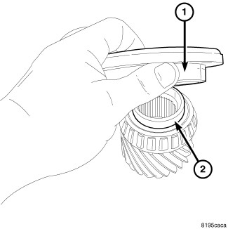
- Remove the oil filter seal (1) at the case.
 Courtesy of CHRYSLER LLC
NOTE:
Keep the Front Sound Dampener Cover if replacing the unit
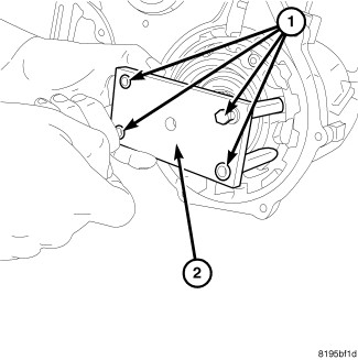
- If equipped remove the fasteners (1) and the Front Sound Dampener Cover (2).
 Courtesy of CHRYSLER LLC
NOTE:
Keep the Top Sound Dampener Cover if replacing the unit
- If equipped remove the Top Sound Damper Cover (1).
 Courtesy of CHRYSLER LLC
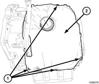
- Remove bolts (2) at the valve body oil pan (1).
 Courtesy of CHRYSLER LLC
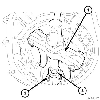
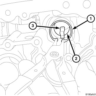
- Remove the pressure tap plug (2) at valve body pan.
- Remove the valve body pan.
 Courtesy of CHRYSLER LLC
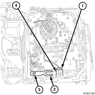
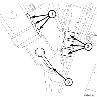
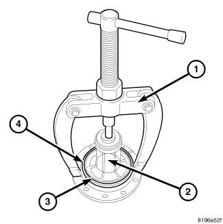
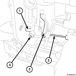
- Remove the electrical connector (1) at the range sensor (4).
- Remove the bolt (3) holding the detent spring.
- Remove the detent spring (2).
 Courtesy of CHRYSLER LLC
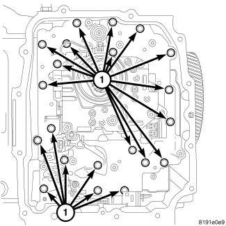
- Remove valve body bolts (1).
 Courtesy of CHRYSLER LLC
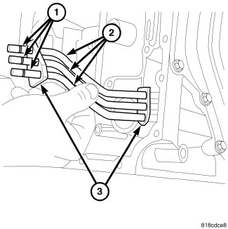
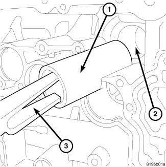
- Remove valve body (1) from oil transfer tubes and manual valve (3) from rooster comb.
 Courtesy of CHRYSLER LLC
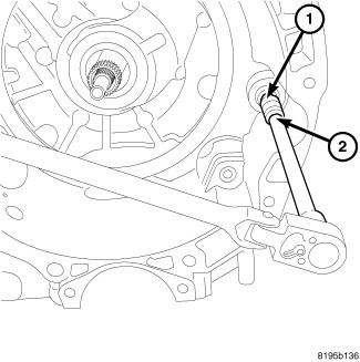
- Remove oil transfer tubes (2) from the case.
 Courtesy of CHRYSLER LLC
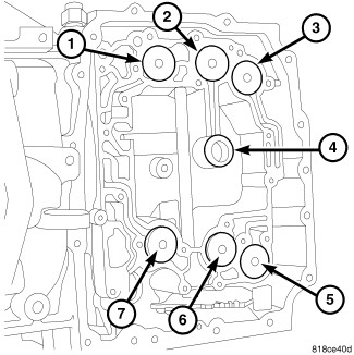
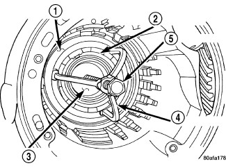
| 1 - UD ACCUMULATOR |
5 - LC ACCUMULATOR |
| 2 - 2/4 ACCUMULATOR |
6 - DC ACCUMULATOR |
| 3 - LR ACCUMULATOR |
7 - OD ACCUMULATOR |
| 4 - 2/4 CLUTCH OIL SUPPLY SEAL |
- |
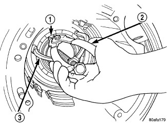
- Remove all six accumulators (1, 2, 3, 5, 6 and 7) from case along with the accumulator return springs.
- Remove the 2/4 clutch oil supply seal (4) from the case.
- Remove the manual lever, TRS and seal. See Transmission and Transfer Case/Automatic - 62TE/SENSOR, Transmission Range - Removal .
 Courtesy of CHRYSLER LLC
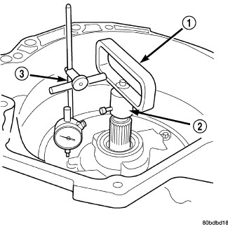
| 1 - END PLAY FIXTURES 8266A |
| 2 - DIAL INDICATOR C-3339A |
- Measure input shaft end play. Place transaxle so input shaft is vertical. Set up end play fixtures 8266A (1,2) and dial indicator (3). Input shaft end play should be within 0.13-0.64 mm (0.005-0.025 in.)
Record indicator reading for reference upon reassembly.
 Courtesy of CHRYSLER LLC
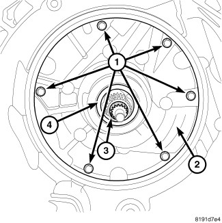
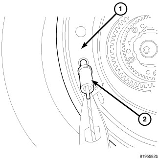
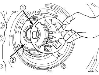
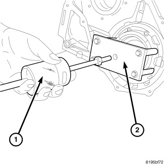
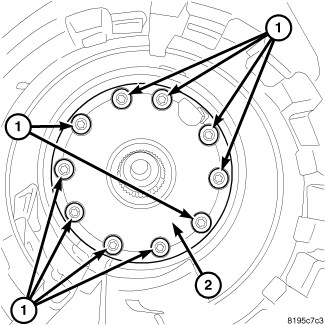
- Remove the front pump bolts (1).
 Courtesy of CHRYSLER LLC
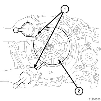
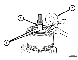
CAUTION:
Be sure input speed sensor is removed before removing oil pump.
- Install slide hammers C-3752 (1) on oil pump.
 Courtesy of CHRYSLER LLC
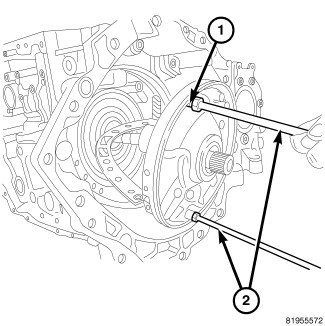
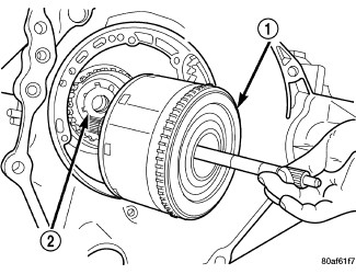
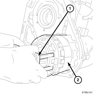
- Remove oil pump assembly (1).
 Courtesy of CHRYSLER LLC
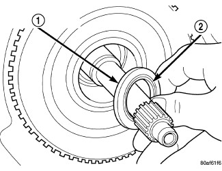
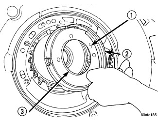
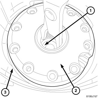
- Remove oil pump gasket (2).
 Courtesy of CHRYSLER LLC
CAUTION:
If transaxle failure has occurred, the cooler bypass valve must be replaced. Do not re-use or attempt to clean valve.
- Remove cooler bypass valve (2).
 Courtesy of CHRYSLER LLC
| 1 - #1 CAGED NEEDLE BEARING |
| 2 - NOTE: TANGED SIDE OUT |
- Remove number one needle bearing (1).
 Courtesy of CHRYSLER LLC
| 1 - INPUT CLUTCH ASSEMBLY |
| 2 - #4 THRUST WASHER |
- Remove input clutch assembly (1).
 Courtesy of CHRYSLER LLC
| 1 - OVERDRIVE SHAFT ASSEMBLY |
| 2 - #4 THRUST PLATE (SELECT) |
| 3 - 3 DABS OF PETROLATUM FOR RETENTION |
- Remove number four thrust plate (2).
 Courtesy of CHRYSLER LLC
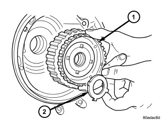
| 1 - FRONT SUN GEAR ASSEMBLY |
| 2 - #4 THRUST WASHER (FOUR TABS) |
- Remove front sun gear assembly (1) and number four thrust washer (2).
 Courtesy of CHRYSLER LLC
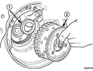
| 1 - #6 NEEDLE BEARING |
| 2 - FRONT CARRIER AND REAR ANNULUS ASSEMBLY (TWIST AND PULL OR PUSH TO REMOVE OR INSTALL). |
- Remove front carrier/rear annulus assembly (2) and number six needle bearing (1).
 Courtesy of CHRYSLER LLC
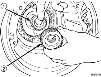
| 1 - #7 NEEDLE BEARING |
| 2 - REAR SUN GEAR |
NOTE:
The number seven needle bearing (1) has three anti-reversal tabs and is common with the number five and number two position. The orientation should allow the bearing to seat flat against the rear sun gear (1) when put together.
- Remove rear sun gear (2) and number seven needle bearing (1).
 Courtesy of CHRYSLER LLC
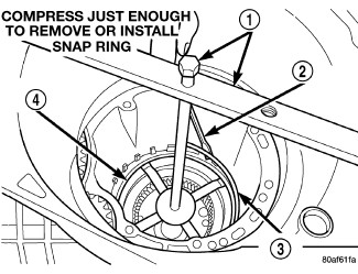
| 1 - SPRING COMPRESSING 5058A |
| 2 - SCREWDRIVER |
| 3 - SNAP RING |
| 4 - 2/4 CLUTCH RETAINER |
NOTE:
Verify that Compressor 5058A is centered properly over the 2/4 clutch retainer before compressing. If necessary, fasten the 5058A bar to the bellhousing flange with any combination of locking pliers and bolts to center the tool properly.
- Setup the Spring Compressor 5058A (1), Compress 2/4 clutch return spring (4) (just enough to remove snap ring) and remove snap ring (3).
 Courtesy of CHRYSLER LLC
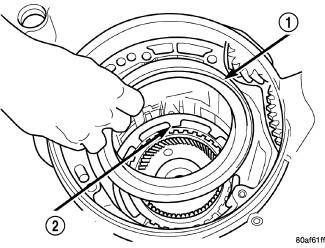
| 1 - 2/4 CLUTCH RETAINER |
| 2 - 2/4 CLUTCH RETURN SPRING |
NOTE:
The 2/4 Clutch Piston has bonded seals which are not individually serviceable. Seal replacement requires replacement of the piston assembly.
- Remove 2/4 clutch retainer (1).
 Courtesy of CHRYSLER LLC
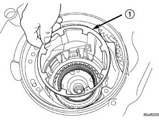
| 1 - 2/4 CLUTCH RETURN SPRING |
- Remove 2/4 clutch return spring (1).
 Courtesy of CHRYSLER LLC
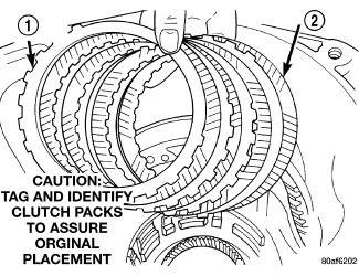
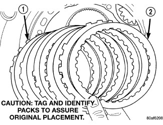
| 1 - CLUTCH PLATE (4) |
| 2 - CLUTCH DISC (4) |
- Remove 2/4 clutch pack (1,2). Tag 2/4 clutch pack for reassembly identification.
 Courtesy of CHRYSLER LLC
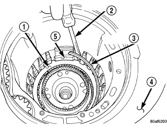
| 1 - LOW/REVERSE CLUTCH REACTION PLATE |
| 2 - SCREWDRIVER |
| 3 - LOW/REVERSE TAPERED SNAP RING (TAPERED SIDE UP) |
| 4 - OIL PAN FACE |
| 5 - LONG TAB |
- Remove tapered snap ring (3).
 Courtesy of CHRYSLER LLC
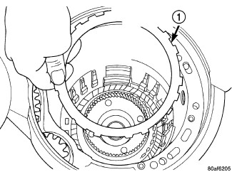
| 1 - LOW/REVERSE REACTION PLATE (FLAT SIDE UP) |
- Remove low/reverse reaction plate (1).
 Courtesy of CHRYSLER LLC
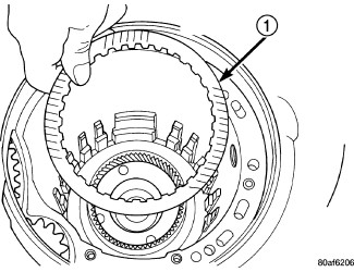
| 1 - ONE DISC FROM LOW/REVERSE CLUTCH |
- Remove one low/reverse clutch disc (1).
 Courtesy of CHRYSLER LLC
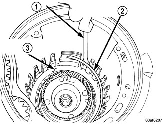
| 1 - SCREWDRIVER |
| 2 - LOW/REVERSE REACTION PLATE FLAT SNAP RING |
| 3 - DO NOT SCRATCH CLUTCH PLATE |
- Remove low/reverse reaction plate snap ring (2).
 Courtesy of CHRYSLER LLC
| 1 - CLUTCH PLATES (5) |
| 2 - CLUTCH DISCS (5) |
- Remove low/reverse clutch pack (1,2).
 Courtesy of CHRYSLER LLC
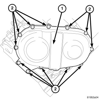
- Remove transfer gear cover-to-case bolts (2).
- Remove transfer gear cover (1).
 Courtesy of CHRYSLER LLC
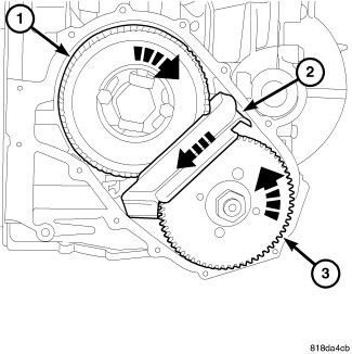
- Remove the oil scavenger (2).
 Courtesy of CHRYSLER LLC
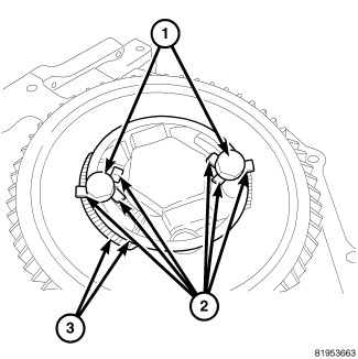
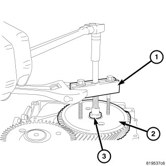
- Bend back the locking tabs (2) at the output transfer gear retaining strap (3).
- Remove the bolts (1) at the output transfer gear retaining strap (3).
- Remove the output transfer gear retaining strap (3).
 Courtesy of CHRYSLER LLC
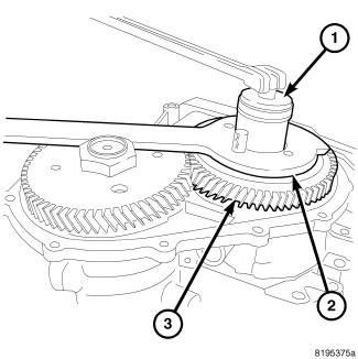
- Install the Gear Holder 9739 (2) onto the output transfer gear (3).
- Remove the output transfer gear bolt (1).
 Courtesy of CHRYSLER LLC
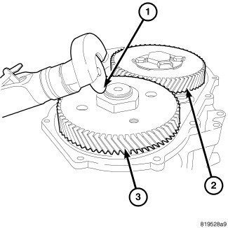
- Grind the staked tabs (1) from the transfer gear (underdrive compounder side).
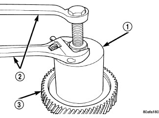
- Install the Gear Holder 9739 (1) onto the transfer gear (underdrive compounder side) and remove the nut.
- Lift the transfer gear from the underdrive compounder shaft.
 Courtesy of CHRYSLER LLC
- Using Gear Puller L-4407A (1) and Thrust Button 6055 (3) remove output shaft transfer gear (2) and select shim.
 Courtesy of CHRYSLER LLC
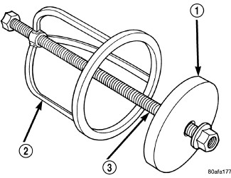
| 1 - BEARING PULLER 5048 WITH JAWS 5048-5 AND THRUST PAD L-4539-2 |
| 2 - WRENCHES |
| 3 - OUTPUT GEAR |
- Using Bearing Puller 5048 with Jaws 5048-5 and Thrust Pad L-4539-2 (1) remove output gear bearing cone.
 Courtesy of CHRYSLER LLC
- Using Press Puller C-293-PA (1), Adaptors 9738 (3) and Press Plug 9678 remove compounder transfer gear bearing cone.
 Courtesy of CHRYSLER LLC
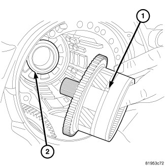
- Remove rear carrier assembly (1) from transaxle (2).
 Courtesy of CHRYSLER LLC
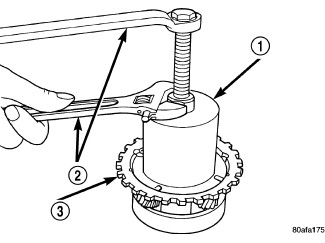
| 1 - BEARING PULLER 5048 WITH JAWS 5048-3 AND THRUST BUTTON 6055 |
| 2 - WRENCHES |
| 3 - REAR CARRIER ASSEMBLY |
- Remove rear carrier assembly (3) bearing cone using bearing puller 5048 with Jaws 5048-3 and thrust button 6055.
 Courtesy of CHRYSLER LLC
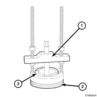
| 1 - SPRING COMPRESSOR DISC 6057 |
| 2 - SPRING COMPRESSOR 5059-A |
| 3 - FORCING SCREW 5058A-3 |
- Install spring compressor disk 6057 (1), spring compressor 5059-A (2) and forcing screw 5058A-3 (3).
 Courtesy of CHRYSLER LLC
| 1 - LOW/REVERSE CLUTCH RETURN SPRING |
| 2 - SNAP RING (INSTALL AS SHOWN IN ILLUSTRATION) |
| 3 - SPRING COMPRESSOR DISC 6057 |
| 4 - SPRING COMPRESSOR 5059-A |
| 5 - FORCING SCREW 5058A-3 |
- Compress low/reverse spring using spring compressor 5059-A (4).
 Courtesy of CHRYSLER LLC
| 1 - SNAP RING OPENING MUST BE BETWEEN SPRING LEVERS (AS SHOWN IN ILLUSTRATION) |
| 2 - SNAP RING PLIERS |
| 3 - SPRING COMPRESSOR DISC 6057 |
- Remove snap ring (1) at low/reverse piston return spring.
 Courtesy of CHRYSLER LLC
| 1 - LOW/REVERSE PISTON RETURN SPRING |
| 2 - PISTON |
- Remove low/reverse spring compressor tool and low reverse piston return spring (1).
 Courtesy of CHRYSLER LLC
| 1 - LOW/REVERSE CLUTCH PISTON |
| 2 - BONDED SEAL |
| 3 - BONDED SEAL |
NOTE:
The Low/Reverse Clutch Piston has bonded seals which are not individually serviceable. Seal replacement requires replacement of the piston assembly.
- Remove low/reverse clutch piston (1).
 Courtesy of CHRYSLER LLC
| 1 - LOW/REVERSE CLUTCH PISTON RETAINER |
| 2 - SCREWDRIVER |
| 3 - TORX-LOC SCREWS |
- Remove low/reverse piston retainer-to-case screws (3).
 Courtesy of CHRYSLER LLC
| 1 - LOW/REVERSE CLUTCH PISTON RETAINER |
| 2 - GASKET |
- Remove low/reverse piston retainer (1).
 Courtesy of CHRYSLER LLC
| 1 - GASKET HOLES MUST LINE UP |
| 2 - LOW/REVERSE CLUTCH PISTON RETAINER GASKET |
- Remove low/reverse piston retainer-to-case gasket (2), gasket holes must line up (1).
 Courtesy of CHRYSLER LLC
- Using a hammer and suitable drift (2), drive out inner output bearing cup (1).
 Courtesy of CHRYSLER LLC
- Using bearing cup puller 6062A (1), remove outer output bearing cup (2).
 Courtesy of CHRYSLER LLC
- Remove the snap ring (1) at the underdrive compounder assembly (2).
 Courtesy of CHRYSLER LLC
- Remove four bolts (1) at the compounder bearing retainer.
 Courtesy of CHRYSLER LLC
- Install puller adapter 9908 (2) to the compounder bearing retainer.
 Courtesy of CHRYSLER LLC
- Install Slide Hammer C-3752 (1) to puller adapter 9908 (2) and pull the underdrive compounder assembly from the case.
 Courtesy of CHRYSLER LLC
NOTE:
Insure that the planetary gear set / output hub is removed as part of the underdrive compounder assembly.
- Remove the underdrive compounder assembly (2).
 Courtesy of CHRYSLER LLC
- Remove the bolts (1) at the remote pinion cover (2).
 Courtesy of CHRYSLER LLC
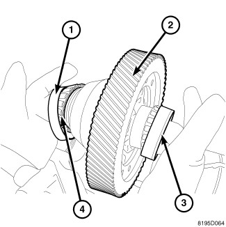
- Remove the remote pinion (1) and the remote pinion cover (2) from the case.
 Courtesy of CHRYSLER LLC
- Remove the remote pinion cover (1) from the remote pinion (2).
 Courtesy of CHRYSLER LLC
- Using Remover 8913 (2) and Brace 8915 (1) remove the remote pinion cover bearing cup (3) and selective shim.
 Courtesy of CHRYSLER LLC
- Using Remover 8912 and Brace 8915 (1, 2) pull remote pinion small bearing cup (3) from the case.
 Courtesy of CHRYSLER LLC
- Remove the differential output bearing cover bolts (1).
- Remove differential output bearing cover (2).
 Courtesy of CHRYSLER LLC
- Remove the differential cover bolts (1).
 Courtesy of CHRYSLER LLC
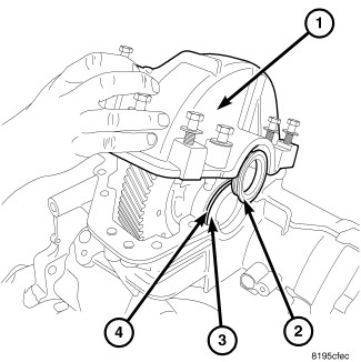
- Remove the differential cover (1).
- Remove the out seal (2), oil singer (3) and the small bearing cup (4).
- Remove the large bearing cup.
 Courtesy of CHRYSLER LLC
- Remove the differential.
- Remove the manual lever and TRS. See Transmission and Transfer Case/Automatic - 62TE/SENSOR, Transmission Range - Removal .
 Courtesy of CHRYSLER LLC
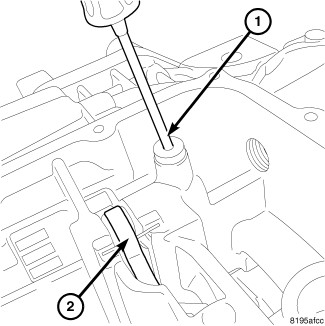
- Remove the set screw (1) for the park pawl shaft.
 Courtesy of CHRYSLER LLC
- Remove the snap ring (1) for the park guide assembly (2).
 Courtesy of CHRYSLER LLC
- Remove the park guide assembly (1).
 Courtesy of CHRYSLER LLC
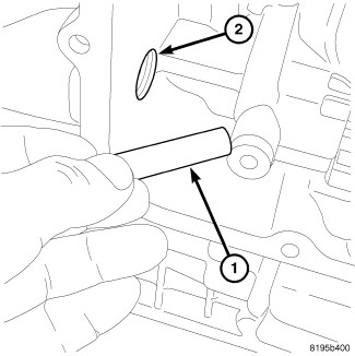
- Remove the plug (1) to allow the park pawl shaft to be removed.
 Courtesy of CHRYSLER LLC
- Slide the shaft (1) out of the park pawl (3).
 Courtesy of CHRYSLER LLC
- Remove the park pawl shaft (1).
 Courtesy of CHRYSLER LLC
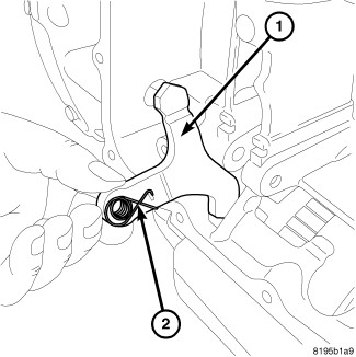
- Remove the park pawl (1) and the park pawl spring (2).