Rectifier Test
- Check rectifier assembly for poor solder joints, cracks or signs of overheating. Clean small area of coating from each diode location to ensure good electrical contact during testing.
- Using an ohmmeter, connect positive test probe to negative diode and negative probe to stator terminal. Resistance should be 7-11 ohms. Move positive test probe to positive diode, no continuity should be detected. Perform same test procedure on each stator terminal to diode set. See Figure and Figure
.
- Connect negative ohmmeter probe to positive diode and positive probe to stator terminal. Resistance should be 7-11 ohms. Move negative test probe to negative diode, continuity should not exist. Perform same test on each stator terminal to diode set. If rectifier does not test as specified, replace rectifier assembly.
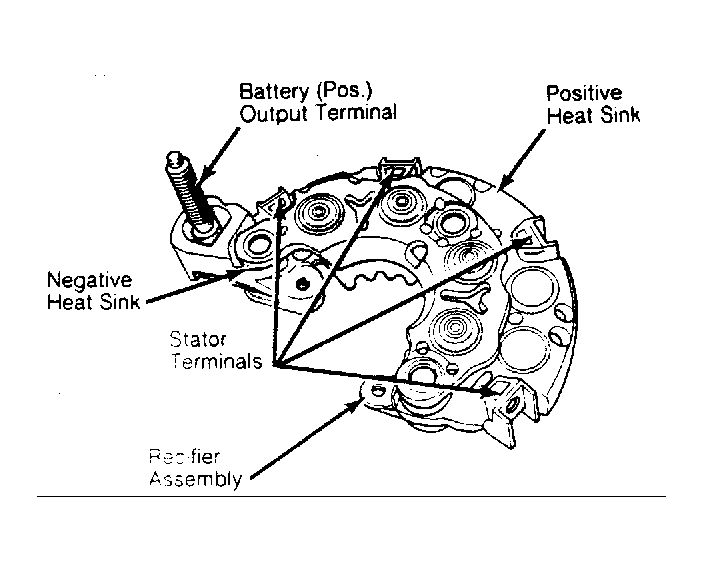 Courtesy of CHRYSLER MOTORS.
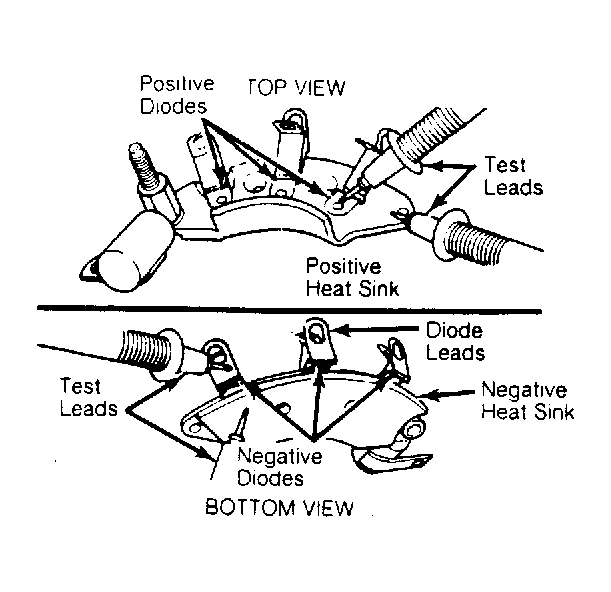 Courtesy of CHRYSLER MOTORS.