Wiper Switch Continuity Test
Check continuity between switch terminals as shown in illustrations. Either a self powered test light or an ohmmeter can be used to test a standard two speed switch. An ohmmeter must be used to test a switch with the intermittent system. To detect marginal operation of switch, rotate knob or slide switch while each reading is being taken. If switch does not exhibit continuity as shown or poor continuity exists, replace switch.
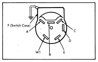 Courtesy of FORD MOTOR CO.
| Switch Position |
Terminals |
| Off (Park) |
C-D, A-B |
| Low |
A-B-C |
| High |
A-B-E |
| Wash |
A-B-W1 |
| Intermittent Switch Position |
Intermittent Terminals |
| Off (Park) |
A-B, D-E |
| Low |
A-B, D-E-F |
| High |
D-E-F, A-B-C |
| Intermittent |
E-F, A-B |
| Wash |
A.B-W1 |
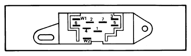 Courtesy of FORD MOTOR CO.
| Switch Position (Non-Interval) |
Terminals |
| Off (Park) |
1-5, 3-7 |
| Low |
1-4, 2-7 |
| High |
1-4, 2-6 |
| Wash |
W1-W2 |
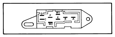 Courtesy of FORD MOTOR CO.
| Switch Position (Interval) |
Terminals |
| Off (Park) |
A-E |
| Low |
B-E-F-C |
| High |
D-B-F-C |
| Intermittent |
B-E-F |
| Wash |
W1-W2 |
NOTE:
Resistance between terminals F-C will vary 500±400 ohms at minimum dwell to 10, 000±2000 at maximum dwell.