All Other Models
- Measure toe-in with front wheels straight ahead, and steering wheel locked in a centered position. Adjust toe-in by loosening clamps, and adjusting sleeve to obtain correct specification and maintain steering wheel in centered position.
- If steering wheel is not centered to begin with, determine which tire assembly is out of adjustment, and compensate that side to center the steering wheel. Multiple attempts may be necessary to properly center steering wheel.
- When tightening clamps, ensure clamp bolts are positioned so there will be no interference with other parts throughout entire travel of steering linkage.
WHEEL ALIGNMENT SPECIFICATIONS (AEROSTAR)
| Application |
Fraction |
Decimal |
| Camber (Degrees) |
7/32 +/- 1/2 |
(.22 +/- .50) |
| Caster (Degrees) |
4 +/- 1 |
(4 +/- 1) |
| Toe-in (Inches) |
1/32 +/- 1/8 |
(.03 +/- .13) |
| Toe-in (Degrees) |
1/16 +/- 1/4 |
(.06 +/- .25) |
WHEEL ALIGNMENT SPECIFICATIONS (EXPLORER)
| Application |
Fraction |
Decimal |
| 2WD |
| Camber (Degrees) |
1/4 +/- 1/2 |
(.25 +/- .50) |
| Caster (Degrees) |
5 +/- 1 |
(5 +/- 1) |
| Toe-in (Inches) |
0 +/- 1/8 |
(0 +/- .13) |
| Toe-in (Degrees) |
0 +/- 1/4 |
(0 +/- .25) |
| 4WD |
| Camber (Degrees) |
1/4 +/- 1/2 |
(.25 +/- .50) |
| Caster (Degrees) |
4 1/4 +/- 1 3/4 |
(4.25 +/- 1.75) |
| Toe-in (Inches) |
0 +/- 1/8 |
(0 +/- .13) |
| Toe-in (Degrees) |
0 +/- 1/4 |
(0 +/- .25) |
WHEEL ALIGNMENT SPECIFICATIONS (RANGER)
| Application |
Fraction |
Decimal |
| 2WD |
| Camber (Degrees) |
|
|
| Caster (Degrees) |
|
|
| Toe-in (Inches) |
1/32 +/- 1/8 |
(.03 +/- .13) |
| Toe-in (Degrees) |
1/16 +/- 1/4 |
(0 +/- .25) |
| 4WD |
| Camber (Degrees) |
|
|
| Caster (Degrees) |
|
|
| Toe-in (Inches) |
1/32 +/- 1/8 |
(.03 +/- .13) |
| Toe-in (Degrees) |
1/16 +/- 1/4 |
(0 +/- .25) |
WHEEL ALIGNMENT SPECIFICATIONS (BRONCO & F150)
| Application |
Fraction |
Decimal |
| 2WD |
| Camber (Degrees) |
|
|
| Caster (Degrees) |
|
|
| Toe-in (Inches) |
1/32 +/- 1/8 |
(.03 +/- .13) |
| Toe-in (Degrees) |
1/16 +/- 1/4 |
(0 +/- .25) |
| 4WD |
| Camber (Degrees) |
|
|
| Caster (Degrees) |
|
|
| Toe-in (Inches) |
1/32 +/- 1/8 |
(.03 +/- .13) |
| Toe-in (Degrees) |
1/16 +/- 1/4 |
(0 +/- .25) |
WHEEL ALIGNMENT SPECIFICATIONS (F250/350)
| Application |
Fraction |
Decimal |
| 2WD |
| Camber (Degrees) |
|
|
| Caster (Degrees) |
|
|
| Toe-in (Inches) |
1/32 +/- 1/8 |
(.03 +/- .13) |
| Toe-in (Degrees) |
1/16 +/- 1/4 |
(0 +/- .25) |
| 4WD |
| Camber (Degrees) |
|
|
| Caster (Degrees) |
|
|
| Toe-in (Inches) |
1/32 +/- 1/8 |
(.03 +/- .13) |
| Toe-in (Degrees) |
1/16 +/- 1/4 |
(0 +/- .25) |
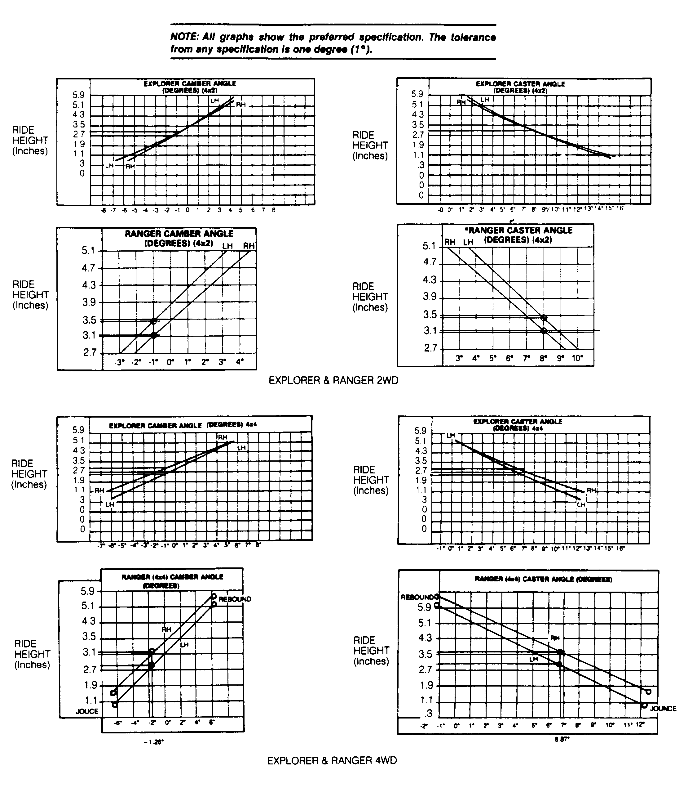 Courtesy of FORD MOTOR CO.