Pinpoint Test D - Wipers Inoperative At Interval Setting
- Turn ignition on. Turn wiper switch to low speed. If wipers operate at low speed, go to next step. If wipers do not operate at low speed, go to PINPOINT TEST B
.
- Turn ignition off. Remove Central Timer Module (CTM) from instrument panel fuse block. Set ohmmeter to 20 k/ohm range. Connect ohmmeter between terminals No. 14 and 17 at CTM connector in fuse block. See Fig 1
. Rotate interval selector control on wiper switch from SLOW to FAST while observing ohmmeter. If resistance varies from 10,000-12,000 ohms, go to step 9). If resistance does not vary from 10,000-12,000 ohms, leave ohmmeter connected and go to next step.
- With ohmmeter still connected as in step 2), recheck circuit resistance. If resistance is more than 20,000 ohms, leave ohmmeter connected and go to next step. If resistance is 20,000 ohms or less, go to step 11).
- Disconnect wiper switch connector. Measure resistance between terminals No. 17 of CTM connector in fuse block and No. 6 (White wire) at wiper switch connector. If resistance is 5 ohms or more, go to next step. If resistance is less than 5 ohms, go to step 6).
- Disconnect instrument panel fuse block connector "N". Measure resistance between terminals No. 17 at CTM connector in fuse block and No. 3 (White wire) at connector "N". See Figure
and Fig 1
. If resistance is less than 5 ohms, repair open in White wire between wiper switch and fuse block. If resistance is 5 ohms or more, replace fuse block and retest system.
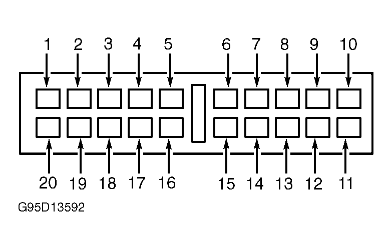 Courtesy of FORD MOTOR CO.
- Measure resistance between terminals No. 14 at CTM connector in instrument panel fuse block and No. 5 (White/Black wire) at wiper switch connector. If resistance is 5 ohms or more, go to next step. If resistance is less than 5 ohms, go to step 8).
- Measure resistance between terminals No. 14 at CTM connector in instrument panel fuse block and No. 4 (White/Black wire) at connector "N". If resistance is less than 5 ohms, repair open in White/Black wire between wiper switch and fuse block. If resistance is 5 ohms or more, replace fuse block and retest system.
- Measure resistance of White/Black wire between terminals No. 5 at connector "N" and No. 4 and wiper switch connector. If resistance is less than 5 ohms, go to next step. If resistance is 5 ohms or more, repair open in White/Black wire.
- Remove interval wiper relay from instrument panel fuse block. Connect an ohmmeter between relay terminals No. 3 and 4. Note resistance reading. See Fig 2
. Also, measure resistance between relay terminals No. 3 and 5. Resistance should be less than 1 ohm between terminals No. 3 and 4. Resistance should be infinite between terminals No. 3 and 5. If resistance is as specified, go to next step. If resistance is not as specified, replace wiper relay and retest system.
- Test interval wiper relay. See INTERVAL WIPER RELAY
under COMPONENT TESTING. If relay operates properly, replace Central Timer Module (CTM). If relay is faulty, replace interval wiper relay and retest system.
- Disconnect instrument panel fuse block connector "N". Check for short circuit between connector terminals No. 3 and 4. See Figure
. If short circuit is still indicated, go to next step. If short circuit is no longer indicated, replace fuse block.
- Disconnect wiper switch connector. Check for short circuit between terminals No. 3 and 4 at connector "N". If short circuit is indicated, repair connector and/or wiring. Retest system. If no short circuit is indicated, replace wiper switch and retest system.
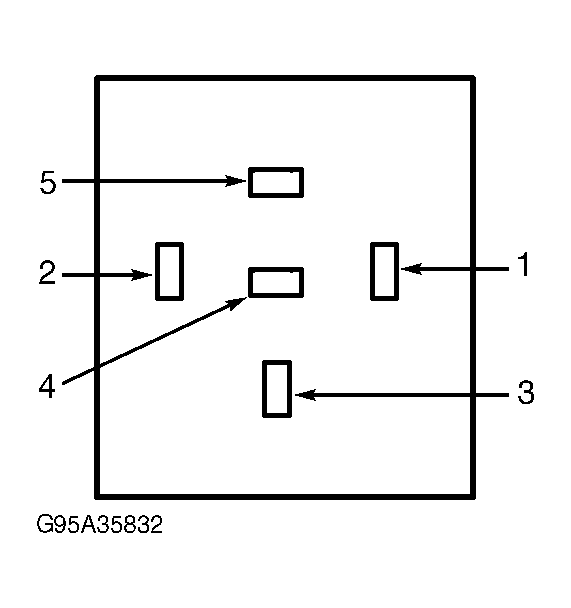 Courtesy of FORD MOTOR CO.