Test D: Flash Code 4 - Vehicle Speed Sensor (VSS) Circuit Failure
- Verify Which ABS System Vehicle Is Equipped With
- Check to see if vehicle is equipped with rear wheel ABS or 4-wheel ABS. If vehicle is equipped with rear wheel ABS, go to next step. If vehicle is equipped with 4-wheel ABS, go to step 11).
- Check Ignition State
- Using NGS tester, monitor GEM/CTM PID IGN_GEM while rotating ignition switch through all positions. If vehicle is equipped with M/T, press clutch pedal when ignition switch is in START position. If PID values agree with ignition switch positions, go to next step. If PID values do not agree with ignition switch positions, check ignition switch. See appropriate STEERING COLUMN SWITCHES article.
- Retrieve DTCs
- Using NGS tester, retrieve continuous DTCs. Clear continuous DTCs and retrieve On-Demand DTCs. If DTC P0500 or no DTCs are retrieved, go to next step. If DTC C1752 is retrieved, go to step 8). If DTC C1751 is retrieved, go to step 10).
- Check Red/Pink & Light Green/Black Wires For Short To Ground
- Disconnect GEM/CTM 18-pin connector C224 (located behind center of instrument cluster). Disconnect ABS control module 14-pin connector C238 (located behind lower center of instrument panel). Disconnect rear ABS sensor connector C421 (located on inside of left front frame rail). Using an ohmmeter, check resistance between ground and GEM/CTM connector C224 terminal No. 9. See Fig 1
. Check resistance between ground and GEM/CTM connector C224 terminal No. 18. If resistances are more than 10 k/ohms, go to next step. If resistances are 10 k/ohms or less, repair appropriate circuit(s) and perform self-test diagnostics using NGS tester.
- Check Red/Pink & Light Green/Black Wires For Open
- Using an ohmmeter, check resistance in Red/Pink wire between GEM/CTM connector C224 terminal No. 9 and rear ABS sensor connector C421 Red/Pink wire terminal. Check resistance in Light Green/Black wire between GEM/CTM connector C224 terminal No. 18 and rear ABS sensor connector C421 Light Green/Black wire terminal. See Fig 1
. If resistances are less than 5 ohms, go to next step. If resistances are 5 ohms or more, repair appropriate circuit(s) and perform self-test diagnostics using NGS tester.
- Check Red/Pink & Light Green/Black Wires For Short To Power
- Using a voltmeter, check voltage between ground and GEM/CTM connector C224 terminal No. 9. Check voltage between ground and GEM/CTM connector C224 terminal No. 18. If no voltage is present, go to next step. If voltage is present, repair appropriate circuit(s) and perform self-test diagnostics using NGS tester.
- Check GEM/CTM PID VSS_GEM
- Using NGS tester, monitor GEM/CTM PID VSS_GEM while driving vehicle between 0-55 MPH. If GEM/CTM PID VSS_GEM value and speedometer indicate more than zero MPH, go to next step. If GEM/CTM PID VSS_GEM value and speedometer do not indicate more than zero MPH, repair or replace rear ABS sensor. See appropriate ANTI-LOCK SYSTEM article in the BRAKES section.
- Check Gray/Black Wire For Short To Ground
- Disconnect instrument cluster 12-pin connector C215 (located behind instrument cluster). Disconnect PCM 104-pin connector C111 (located near center of safety wall). Disconnect speed control servo/actuator connector C165 (located in right rear of engine compartment). Disconnect GEM/CTM 18-pin connector C224 (located behind center of instrument cluster). Using an ohmmeter, check resistance between ground and GEM/CTM connector C224 terminal No. 1. See Fig 1
. If resistance is more than 10 k/ohms, go to next step. If resistance is 10 k/ohms or less, repair short to ground in Gray/Black wire and perform self-test diagnostics using NGS tester.
- Check Gray/Black Wire For Open
- Using an ohmmeter, check resistance in Gray/Black wire between GEM/CTM connector C224 terminal No. 1 and speed control servo/actuator connector C165 terminal No. 3. See Figure
and Fig 1
. If resistance is less than 5 ohms, go to next step. If resistance is 5 ohms or more, repair open in Gray/Black wire and perform self-test diagnostics using NGS tester.
- Check Gray/Black Wire For Short To Power
- Using a voltmeter, check voltage between ground and GEM/CTM connector C224 terminal No. 1. If voltage is present, repair short to power in Gray/Black wire and perform self-test diagnostics using NGS tester. If no voltage is present, replace speed control servo/actuator and perform self-test diagnostics using NGS tester.
- Check Speedometer Operation
- Test drive vehicle while observing speedometer operation. If speedometer operates properly, go to next step. If speedometer does not operate properly, see appropriate INSTRUMENT PANEL article to continue diagnosis.
- Check Gray/Black Wire For Open
- Turn ignition off. Disconnect ABS control module connector C154 (located near left front fenderwell). Using an ohmmeter, check resistance in Gray/Black wire between speed control servo/actuator connector C165 terminal No. 3 and ABS control module connector C154 terminal No. 10. See Figure
and Fig 2
. If resistance is less than 5 ohms, replace speed control servo/actuator and perform self-test diagnostics using NGS tester. If resistance is 5 ohms or more, repair open in Gray/Black wire and perform self-test diagnostics using NGS tester.
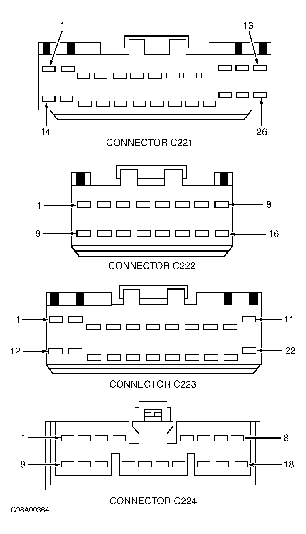 Courtesy of FORD MOTOR CO.
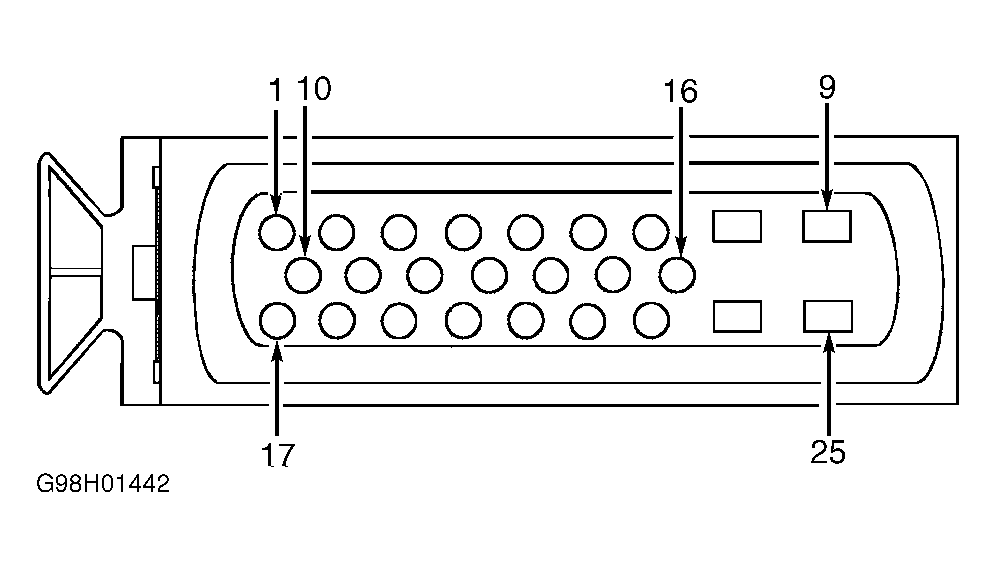 Courtesy of FORD MOTOR CO.