Test B: Driver Window Does Not Operate (Passenger Window Operates)
- Turn ignition off. Using NGS tester, access GEM/CTM PID IGN_GEM/CTM. Monitor GEM/CTM PID IGN_GEM/CTM while rotating ignition switch through START, RUN, OFF and ACC positions. If PID values agree with ignition switch positions, go to next step. If PID values do not agree with ignition switch positions, check ignition switch and retest system operation. See
STEERING COLUMN SWITCHES - RANGER article. Replace switch as necessary. If switch is okay, check ignition switch circuits. See appropriate wiring diagram in POWER DISTRIBUTION article in WIRING DIAGRAMS.
- Using NGS tester, retrieve and record continuous DTCs from GEM/CTM. Using NGS tester, clear continuous DTCs and perform GEM/CTM On-Demand Self-Test. If DTCs B1398 and/or B1400 are recorded, go to next step. If DTCs B1404 and/or B1410 are recorded, go to step 9
. If DTC B1405 is recorded, go to step 12
. If no DTCs are recorded, go to step 13
. If DTC B1342 is recorded, replace GEM/CTM. Clear DTCs and retest system operation.
- Turn ignition switch to RUN position. Using NGS tester, trigger GEM/CTM active command ACCY RLY on. Monitor GEM/CTM PID D_PWRLY while triggering GEM/CTM active command ONE TOUCH on and off. If GEM/CTM PID D_PWRLY value agrees with command mode, go to step 9
. If NGS tester indicates OFFO-G, go to next step. If NGS tester indicates ON-B-, go to step 7
.
- Turn ignition off. Check one-touch down relay. See ONE-TOUCH DOWN RELAY
under COMPONENT TESTS. If one-touch down relay is okay, go to next step. If one-touch down relay does not test as specified, replace one-touch down relay. Clear DTCs and retest system operation.
- Remove delayed accessory relay (located under right side of instrument panel, behind glove box). Using an ohmmeter, check resistance in Light Blue/Black wire between delayed accessory relay connector terminal No. 30 and one-touch down relay connector terminal No. 1. See Figure
and Fig 1
. Check resistance in Light Blue/Black wire between delayed accessory relay connector terminal No. 30 and one-touch down relay connector terminal No. 5. If resistances are less than 5 ohms, go to next step. If either resistance is 5 ohms or more, repair open in appropriate Light Blue/Black wire. Clear DTCs and retest system operation.
- Disconnect 18-pin GEM/CTM connector C224 (located behind center of instrument panel). Using an ohmmeter, check resistance in Yellow/Red wire between one-touch down relay connector terminal No. 2 and 18-pin GEM/CTM connector C224 terminal No. 7. See Figure
and Fig 1
. If resistance is less than 5 ohms, replace GEM/CTM. Clear DTCs and retest system operation. If resistance is 5 ohms or more, repair open in Yellow/Red wire. Clear DTCs and retest system operation.
- Turn ignition off. Check one-touch down relay. See ONE-TOUCH DOWN RELAY
under COMPONENT TESTS. If one-touch down relay is okay, go to next step. If one-touch down relay does not test as specified, replace one-touch down relay. Clear DTCs and retest system operation.
- Disconnect 18-pin GEM/CTM connector C224 (located behind center of instrument panel). Turn ignition switch to RUN position. Using a voltmeter, check voltage between ground and one-touch down relay connector terminal No. 2 (Yellow/Red wire). See Fig 1
. If any voltage is present, repair short to power in Yellow/Red wire. Clear DTCs and retest system operation. If voltage is not present, replace GEM/CTM. Clear DTCs and retest system operation.
- Turn ignition off. Remove and disconnect master window switch connector C502. See POWER WINDOW SWITCH
under REMOVAL & INSTALLATION. Using NGS tester, access GEM/CTM PID D_PW_SW. Connect a jumper wire between ground and master window switch connector C502 terminal No. 6 (White/Black wire). Connect another jumper wire between battery voltage and master window switch connector C502 terminal No. 3 (Tan/Light Blue wire). Turn ignition switch to RUN position. If NGS tester does not indicate DOWN, remove jumper wires and go to next step. If NGS tester indicates DOWN, replace master window switch. Clear DTCs and retest system operation.
- Disconnect 18-pin GEM/CTM connector C224 (located behind center of instrument panel). Using an ohmmeter, check resistance in Tan/Light Blue wire between 18-pin GEM/CTM connector C224 terminal No. 3 and master window switch connector C502 terminal No. 3. If resistance is less than 5 ohms, go to next step. If resistance is 5 ohms or more, repair open in Tan/Light Blue wire. Clear DTCs and retest system operation.
- Using an ohmmeter, check resistance between ground and 18-pin GEM/CTM connector C224 terminal No. 3 (Tan/Light Blue wire). If resistance is more than 10 k/ohms, replace GEM/CTM and retest system operation. If resistance is 10 k/ohms or less, repair short to ground in Tan/Light Blue wire. Clear DTCs and retest system operation.
- Turn ignition off. Remove and disconnect master window switch connector C502. See POWER WINDOW SWITCH
under REMOVAL & INSTALLATION. Disconnect 18-pin GEM/CTM connector C224. Turn ignition switch to RUN position. Using a voltmeter, check voltage between ground and 18-pin GEM/CTM connector terminal No. 3 (Tan/Light Blue wire). If any voltage is present, repair short to voltage in Tan/Light Blue wire. Clear DTCs and retest system operation. If voltage is not present, replace GEM/CTM and retest system operation.
- Turn ignition off. Disconnect driver door window motor connector C504. See POWER WINDOW MOTOR
under REMOVAL & INSTALLATION. Turn ignition switch to RUN position. Using a voltmeter, check voltage between ground and driver door window motor connector C504 Red wire terminal while holding master window switch driver door window in DOWN position. If voltage is more than 10 volts, go to step 16
. If voltage is 10 volts or less, go to next step.
- Turn ignition off. Remove one-touch down relay (located in relay module, on left side of glove box). Using an ohmmeter, check resistance in Red wire between one-touch down relay connector terminal No. 3 and driver door window motor connector. If resistance is less than 5 ohms, go to next step. If resistance is 5 ohms or more, repair open in Red wire. Clear DTCs and retest system operation.
- Remove and disconnect master window switch connector C502. See POWER WINDOW SWITCH
under REMOVAL & INSTALLATION. Using an ohmmeter, check resistance in Tan/Light Blue wire between master window switch connector C502 terminal No. 3 and one-touch down relay connector terminal No. 4. If resistance is less than 5 ohms, replace one-touch down relay. Clear DTCs and retest system operation. If resistance is 5 ohms or more, repair open in Tan/Light Blue wire. Clear DTCs and retest system operation.
- Using a voltmeter, check voltage between ground and driver door window motor connector C504 White/Black wire terminal while holding master window switch driver door window in UP position. If voltage is more than 10 volts, replace driver door window motor. Clear DTCs and retest system operation. If voltage is 10 volts or less, repair White/Black wire. Clear DTCs and retest system operation.
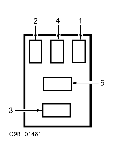 Courtesy of FORD MOTOR CO.