Test F: Wipers Do Not Park Properly
- Turn ignition switch to LOCK position. Remove wiper relay from central junction box. Turn ignition switch to RUN position. Measure voltage at terminal No. 4 at wiper relay socket C72. See Figure
. If battery voltage exists, go to next step. If battery voltage does not exist, go to step 3
.
- Test wiper relay. See WIPER RELAY
under COMPONENT TESTS. If relay is okay, replace wiper/washer switch. If wiper relay is defective, replace wiper relay.
- Turn ignition switch to LOCK position. Disconnect wiper motor harness connector C848. Turn ignition switch to RUN position. Measure voltage at terminal No. 4 (Green/Red wire on 2000 models; Violet wire on 1999 models) at wiper motor harness connector C848. See Figure
. If battery voltage does not exist, go to next step. If battery voltage exists, go to step 5
.
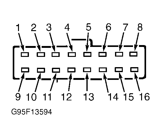
- Turn ignition switch to LOCK position. Disconnect central junction box harness connector C369. Measure resistance of (Green/Red wire on 2000 models; Violet wire on 1999 models) between terminal No. 8 at central junction box harness connector C369 and terminal No. 4 at wiper motor harness connector C848. See Figure
and Fig 1
. If resistance is 5 ohms or less, replace central junction box. If resistance is more than 5 ohms, repair open in Green/Red wire on 2000 models or Violet wire on 1999 models between central junction box and wiper motor.
- Turn ignition switch to LOCK position. Disconnect central junction box harness connector C369. Measure resistance of White/Blue wire between terminal No. 4 at central junction box harness connector C369 and terminal No. 5 at wiper motor harness connector C848. See Figure
and Fig 1
. Resistance should be 5 ohms or less. Measure resistance between ground and terminal No. 5 (White/Blue wire) at wiper motor harness connector C848. Resistance should be more than 10 k/ohms. If resistance is as specified, go to next step. If resistance is not as specified, repair open and/or short to ground in White/Blue wire between central junction box and wiper motor.
- Turn ignition switch to LOCK position. Measure resistance between ground and terminal No. 3 (Black wire) at wiper motor harness connector C848. If resistance is 5 ohms or less, go to next step. If resistance is more than 5 ohms, repair open in Black wire between wiper motor, splice S3003 and ground G22 (located on left front of engine compartment).
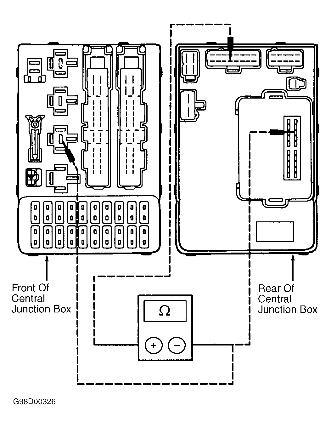
- Remove central timer module from rear of central junction box. Measure resistance between terminal No. 13 at central timer module connector C23 and terminal No. 4 at wiper relay socket C72. Measure resistance between terminal No. 4 at wiper relay socket C72 and terminal No. 4 at central junction box connector C369 (fuse box side). See Fig 2
. If both resistance readings are 5 ohms or less, go to next step. If either resistance reading is more than 5 ohms, replace central junction box.
- Test wiper motor. See WIPER MOTOR
under COMPONENT TESTS. If wiper motor is defective, replace wiper motor. If wiper motor is okay, replace central timer module.
 Courtesy of FORD MOTOR CO.
 Courtesy of FORD MOTOR CO.