Test C: Alarm System Does Not Operate Correctly
- Turn ignition off. Remove and inspect fuse No. 25 (20-amp) from central junction box. If fuse is okay, install fuse and go to next step. If fuse is blown, replace fuse. If fuse blows again, replace fuse and repair short to ground in power distribution circuit. See
POWER DISTRIBUTION article in WIRING DIAGRAMS.
- Open left front window. Arm anti-theft system. Open left front door to trigger anti-theft system, without using key or Remote Keyless Entry (RKE) transmitter. Repeat test for each door. If alarm system operates correctly, go to next step. If alarm does not activate for left front door, go to step 15
. If alarm does not activate for right front door, go to step 17
. If alarm does not activate for left rear door, go to step 19
. If alarm does not activate for right rear door, go to step 21
. If horn does not operate, go to step 7
. If headlights and brakelights do not operate, go to step 9
. If headlights do not operate but brakelights do, go to step 10
. If brakelights do not operate but headlights do, go to step 12
.
- Arm anti-theft system. Open luggage compartment. If alarm does not activate, go to next step. If alarm activates, go to step 7
.
- Disconnect anti-theft/central locking control module connector C451A, and luggage compartment light switch connector C798. Measure resistance of Black/Red wire between terminal No. 8 at anti-theft/central locking module connector C451A and terminal No. 5 at luggage compartment light switch connector C798. See Figure
. If resistance is 5 ohms or less, go to next step. If resistance is greater than 5 ohms, repair open in Black/Red wire. Retest system operation.
- Measure resistance between ground and terminal No. 4 (Black wire) at luggage compartment light switch connector C798. If resistance is 5 ohms or less, go to next step. If resistance is greater then 5 ohms, repair open in
- Test luggage compartment light switch. If switch is defective, replace luggage compartment light switch. If switch is okay, replace anti-theft/central locking control module.
- Check horn operation by pressing steering wheel horn switch. If horn operates properly, go to next step. If horn does not operate properly, repair horn as necessary. See appropriate WIRING DIAGRAMS in STEERING COLUMN SWITCHES - CONTOUR & MYSTIQUE article.
- Disconnect anti-theft/central locking module connector C451A. Connect a jumper wire between anti-theft/central locking module connector C451A terminal No. 1 (Black/White wire) and ground. If horn sounds, replace anti-theft/central locking module. Retest system operation. If horn does not sound, repair open in Black/White wire between anti-theft/central locking module and battery junction box. Retest system operation.
- Disconnect anti-theft/central locking control module connector C451B. Connect a jumper wire between anti-theft/central locking module connector C451B terminal No. 3 (Black/Red wire) and ground. If headlights and brakelights come on, replace anti-theft/central locking module. If headlights and brakelights do not come on, repair open in Black/Red wire. Retest system operation.
- Disconnect panic alarm headlight relay connector C1904 located behind in center of "A" pillar. Measure voltage at terminals No. 1 (Orange/Green wire) and No. 5 (Orange/White wire) at panic alarm headlight relay harness connector C1904. See Fig 1
. If voltages are greater than 10 volts, go to next step. If either voltage is less than 10 volts, repair open in Orange/White and/or Orange/Green wire(s). Retest system operation.
- Test panic alarm headlight relay. See RELAYS
under COMPONENT TESTS. If relay is defective, replace panic alarm headlight relay. If relay is okay, repair open in Orange/White and/or Orange wire panic alarm headlight relay and central junction box. Retest system operation.
- Disconnect panic alarm brakelight relay connector C1910 located in center of "A" pillar. Measure voltage at terminals No. 1 (Orange/Yellow wire) and No. 5 (Orange wire) at panic alarm brakelight relay connector C1910. See Fig 1
. If voltages are greater than 10 volts, go to next step. If either voltage is less than 10 volts, repair open in Orange and/or Orange/Yellow wire(s). Retest system operation.
- Ensure panic alarm headlight relay connector C1904 is disconnected. Measure resistance between panic alarm headlight relay connector C1904 terminal No. 2 (Black/Yellow wire) and panic alarm stoplight relay connector C1910 terminal No. 2 (Black/Yellow wire). If resistance is 5 ohms or less, go to next step. If resistance is greater than 5 ohms, repair open in Black/Yellow wire. Retest system operation.
- Test panic alarm brakelight relay. See RELAYS
under COMPONENT TESTS. If relay is okay, repair open in Orange wire. Retest system operation. If relay is defective, replace panic alarm stoplight relay. Retest system operation.
- Turn ignition off. Disconnect anti-theft/central locking module connector C451A. Open left front door. Measure resistance between anti-theft/central locking module connector C451A terminal No. 9 (Black/Yellow wire) and ground. If resistance is 5 ohms or less, go to next step. If resistance is greater than 5 ohms, replace anti-theft/central locking module. Retest system operation.
- Disconnect left front door ajar switch connector C818. Measure resistance between anti-theft/central locking module connector C451A terminal No. 9 (Black/Yellow wire) and ground. If resistance is greater than 10 k/ohms, replace left front door ajar switch. Retest system operation. If resistance is less than 10 k/ohms, repair short to ground in Black/Yellow wire. Retest system operation.
- Disconnect anti-theft/central locking module connector C451B. Open right front door. Measure resistance between anti-theft/central locking module connector C451B terminal No. 9 (Black/Blue wire) and ground. If resistance is 5 ohms or less, go to next step. If resistance is greater than 5 ohms, replace anti-theft/central locking module.
- Disconnect right front door ajar switch. Measure resistance between anti-theft/central locking module connector C451B terminal No. 9 (Black/Blue wire) and ground. If resistance is greater than 10 k/ohms, replace right front door ajar switch. Retest system operation. If resistance is less than 10 k/ohms, repair short to ground in Black/Blue wire. Retest system operation.
- Disconnect anti-theft/central locking module connector C451A. Open left rear door. Measure resistance between anti-theft/central locking module connector C451A terminal No. 11 (Black/Orange wire) and ground. If resistance is 5 ohms or less, go to next step. If resistance is greater than 5 ohms, replace anti-theft/central locking module. Retest system operation.
- Disconnect left rear door ajar switch connector. Measure resistance between anti-theft/central locking module connector C451A terminal No. 11 (Black/Orange wire) and ground. If resistance is greater than 10 k/ohms, replace left rear door ajar switch. If resistance is less than 10 k/ohms, repair short to ground in Black/Orange wire between left rear door ajar switch and anti-theft/central locking module. Retest system operation.
- Disconnect anti-theft/central locking module connector C451B. Open right rear door. Measure resistance between anti-theft/central locking module connector C451B terminal No. 11 (Black/Green wire) and ground. If resistance is 5 ohms or less, go to next step. If resistance is greater than 5 ohms, replace anti-theft/central locking module. Retest system operation.
- Disconnect right rear door ajar switch. Measure resistance between anti-theft/central locking module connector C451B terminal No. 11 (Black/Green wire) and ground. If resistance is greater than 10 k/ohms, replace right rear door ajar switch. If resistance is less than 10 k/ohms, repair short to ground in Black/Green and/or Black/Orange wire. Retest system operation.
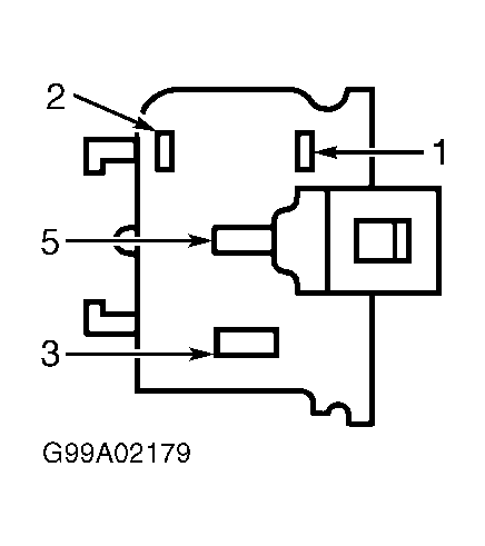 Courtesy of FORD MOTOR CO.