Test J: Panel/Floor Control Does Not Operate Using Auxiliary Controls
- Turn ignition switch to RUN position. Turn front auxiliary blower control switch to HI position. Rotate front auxiliary mode control switch from panel to floor. If front mode control operates properly, go to next step. If front mode control does not operate properly, go to step 8.
- Turn front auxiliary blower motor switch to REAR position. Place rear auxiliary blower motor switch to HI position. Turn rear auxiliary mode control switch from panel to floor. If rear mode control operates properly, system is okay at this time. If rear mode control does not operate properly, go to next step.
- Turn ignition off. Remove rear auxiliary climate control assembly. Disconnect rear auxiliary mode control switch 3-pin harness connector C961. Disconnect auxiliary climate control module 10-pin harness connector C353. Measure resistance of Pink/Light Green wire between rear auxiliary mode control switch harness connector C961 terminal No. 2 and auxiliary climate control module harness connector C353 terminal No. 1. See Figure and Figure
. Measure resistance between ground and auxiliary climate control module harness connector C353 terminal No. 1 (Pink/Light Green wire). If resistance is less than 5 ohms between rear auxiliary mode control switch and auxiliary climate control module and more than 10 k/ohms between ground and climate control module, go to next step. If resistances are not as specified, repair open or short in Pink/Light Green wire. See WIRING DIAGRAMS . Recheck system operation.
- Disconnect auxiliary mode door actuator 8-pin harness connector C355. Measure resistance of Brown/White wire between rear auxiliary mode control switch harness connector C961 terminal No. 3 and auxiliary mode door actuator harness connector C355 terminal No. 6. If resistance is less than 5 ohms, go to next step. If resistance is 5 ohms or more, repair open or high resistance in Brown/White wire. See WIRING DIAGRAMS . Recheck system operation.
- Measure resistance in Gray/Light Blue wire between rear auxiliary mode control switch harness connector C961 terminal No. 1 and auxiliary mode door actuator harness connector C355 terminal No. 4. See Figure and Figure
. If resistance is less than 5 ohms, go to next step. If resistance is 5 ohms or more, repair open or high resistance in Gray/Light Blue wire. See WIRING DIAGRAMS . Recheck system operation.
- Measure resistance between rear auxiliary mode control switch terminals No. 1 and 3. See Fig 1. If resistance is between 4-6 k/ohms, go to next step. If resistance is not 4-6 k/ohms, replace rear auxiliary mode control switch. Recheck system operation.
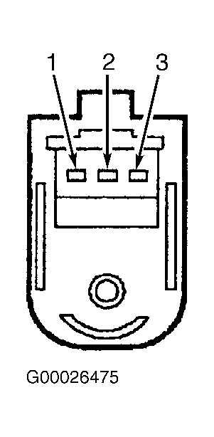 Courtesy of FORD MOTOR CO.
- Measure resistance between rear auxiliary mode control switch terminals No. 1 and 2 while rotating rear auxiliary mode control switch. If resistance varies, replace auxiliary climate control module. Recheck system operation. If resistance does not vary, replace rear auxiliary mode control switch. Recheck system operation.
- Set front auxiliary blower motor switch in REAR position. Set rear auxiliary blower motor switch to HI position. Rotate rear auxiliary mode control switch from panel to floor. If rear mode control operates properly, go to next step. If rear mode control does not operate properly, go to step 14.
- Turn ignition off. Remove front auxiliary control assembly. Disconnect front auxiliary mode control switch 3-pin harness C973. Disconnect auxiliary climate control module 10-pin harness connector C353. Measure resistance of Yellow/White wire between front auxiliary mode control switch harness connector C973 terminal No. 2 and auxiliary climate control module harness connector C353 terminal No. 10. See Figureand Figure. Measure resistance between ground and auxiliary climate control module harness connector C353 terminal No. 10 (Yellow/White wire). If resistance is less than 5 ohms between front auxiliary mode control switch and auxiliary climate control module and more than 10 k/ohms between ground and auxiliary control module, go to next step. If resistances are not as specified, repair open or short in Yellow/White wire. See WIRING DIAGRAMS . Recheck system operation.
- Disconnect auxiliary mode door actuator 8-pin harness connector C355. Measure resistance of Brown/White wire between front auxiliary mode control switch harness connector C973 terminal No. 3 and auxiliary mode door actuator harness connector C355 terminal No. 6. See Figureand Figure
. If resistance is less than 5 ohms, go to next step. If resistance is 5 ohms or more, repair open or high resistance in Brown/White wire. See WIRING DIAGRAMS . Recheck system operation.
- Measure resistance of Gray/Light Blue wire between front auxiliary mode control switch harness connector C973 terminal No. 1 and auxiliary mode door actuator harness connector C355 terminal No. 4. If resistance is less than 5 ohms, go to next step. If resistance is 5 ohms or more, repair open or high resistance in Gray/Light Blue wire. See WIRING DIAGRAMS . Recheck system operation.
- Measure resistance between front auxiliary mode control switch terminals No. 1 and 3. See Fig 1. If resistance is 4-6 k/ohms, go to next step. If resistance is not 4-6 k/ohms, replace front auxiliary mode control switch. Recheck system operation.
- Measure resistance between front auxiliary mode control switch terminals No. 1 and 2 while rotating front auxiliary mode control switch. If resistance varies, replace auxiliary climate control module. If resistance does not vary, replace front auxiliary mode control switch. Recheck system operation.
- Turn ignition off. Disconnect auxiliary mode door actuator 8-pin harness connector C355. Turn ignition switch to RUN position. Measure voltage between ground and auxiliary mode door actuator harness connector C355 terminal No. 7 (Light Blue/Pink wire). See Figure. If more than 10 volts exists, go to next step. If 10 volts or less exists, repair open in Light Blue/Pink wire between auxiliary mode door actuator and auxiliary climate control module. See WIRING DIAGRAMS . Recheck system operation.
- Turn ignition off. Measure resistance between ground and auxiliary mode door actuator harness connector C355 terminal No. 8 (Black wire). If resistance is less than 5 ohms, go to next step. If resistance is 5 ohms or more, repair open or high resistance in Black wire. See WIRING DIAGRAMS . Recheck system operation.
- Disconnect auxiliary climate control module 10-pin harness connector C353. Measure resistance of Light Green wire between auxiliary climate control module harness connector C353 terminal No. 3 and auxiliary mode door actuator harness connector C355 terminal No. 3. See Figure. Measure resistance between ground and auxiliary mode door actuator harness connector C355 terminal No. 3 (Light Green wire). If resistance is less than 5 ohms between auxiliary climate control module and auxiliary mode door actuator and more than 10 k/ohms between ground and auxiliary mode door actuator, go to next step. If resistance is not as specified, repair open or short in Light Green wire. See WIRING DIAGRAMS . Recheck system operation.
- Disconnect front auxiliary mode control switch 3-pin harness connector C973. Disconnect rear auxiliary mode control switch 3-pin harness connector C961. Measure resistance of Brown/White wire between rear auxiliary mode door actuator harness connector C355 terminal No. 6 and rear auxiliary mode control switch harness connector C961 terminal No. 3. See Figure and Figure
. Measure resistance between ground and auxiliary mode door actuator harness connector C355 terminal No. 6 (Brown/White wire). If resistance is less than 5 ohms between auxiliary mode door actuator and rear auxiliary mode control switch and more than 10 k/ohms between ground and auxiliary mode door actuator, go to next step. If resistances are not as specified, repair open or short in Brown/White wire. See WIRING DIAGRAMS . Recheck system operation.
- Measure resistance of Gray/Light Blue wire between auxiliary mode door actuator harness connector C355 terminal No. 4 and rear auxiliary mode control switch harness connector C961 terminal No. 1. See Figure and Figure
. Measure resistance between ground and auxiliary mode door actuator harness connector C355 terminal No. 4 (Gray/Light Blue wire). If resistance is less than 5 ohms between auxiliary mode door actuator and rear auxiliary mode control switch and more than 10 k/ohms between ground and auxiliary mode door actuator, go to next step. If resistance is not as specified, repair open or short in Gray/Light Blue wire. See WIRING DIAGRAMS . Recheck system operation.
- Measure resistance between ground and auxiliary climate control module harness connector C353 terminal No. 1 (Pink/Light Green wire). See Figure. If resistance is less than 5 ohms, go to next step. If resistance is 5 ohms or more, repair open or high resistance in Pink/Light Green wire between auxiliary climate control module and rear auxiliary mode control switch. See WIRING DIAGRAMS . Recheck system operation.
- Measure resistance between ground and auxiliary climate control module harness connector C353 terminal No. 10 (Yellow/White wire). If resistance is more than 10 k/ohms, go to next step. If resistance is less than 10 k/ohms, repair short to ground in Yellow/White wire between auxiliary climate control module and front auxiliary mode control switch. See WIRING DIAGRAMS . Recheck system operation.
- Reconnect auxiliary mode door actuator harness connector C355. Turn ignition switch to RUN position. Turn front auxiliary blower motor switch to HI position. Connect a fused jumper wire between auxiliary climate control module harness connector C353 terminals No. 8 (Light Blue/Pink wire) and No. 3 (Light Green wire). If auxiliary mode door actuator directs airflow to panel, replace auxiliary climate control module. Recheck system operation. If auxiliary mode door actuator does not direct airflow to panel, go to next step.
- Connect a fused jumper between auxiliary climate control module harness connector C353 terminals No. 3 (Light Green wire) and No. 6 (Black wire). If auxiliary mode door directed airflow to floor, replace auxiliary climate control module. Recheck system operation. If auxiliary mode door does not direct airflow to floor, replace auxiliary mode door actuator. Recheck system operation.