MULTIFUNCTION Switch
Remove and disconnect multifunction switch. See MULTIFUNCTION SWITCH under REMOVAL & INSTALLATION. Measure resistance between specified terminals while operating multifunction switch lever to positions as specified. See Fig 1
. See MULTIFUNCTION SWITCH TESTING
table. If resistance is not as specified, replace multifunction switch.
MULTIFUNCTION SWITCH TESTING
| Switch Position |
Between Terminals No. |
Ohms |
| Wiper Switch |
| Off |
685 & 993 |
9550 |
| Intermittent |
685 & 993 |
1910 |
| Low |
685 & 993 |
401 |
| High |
685 & 993 |
0-4 |
| Interval Time Adjust |
590 & 993 |
|
| Washer Switch |
| On |
590 & 993 |
0-4 |
| Hazard Switch |
| On |
2 & 385 |
0-4 |
| On |
3 & 385 |
0-4 |
| Turn Signal Switch |
| Left Turn Signal On |
3 & 44 |
0-4 |
| Right Turn Signal On |
5 & 44 |
0-4 |
| Dimmer Switch |
| High Beam On |
12 & 196 |
0-4 |
| Low Beam On |
15 & 507 |
0-4 |
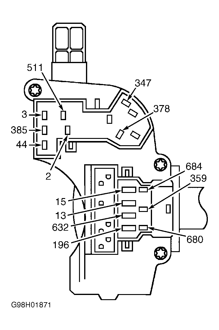 Courtesy of FORD MOTOR CO.