Pinpoint Test
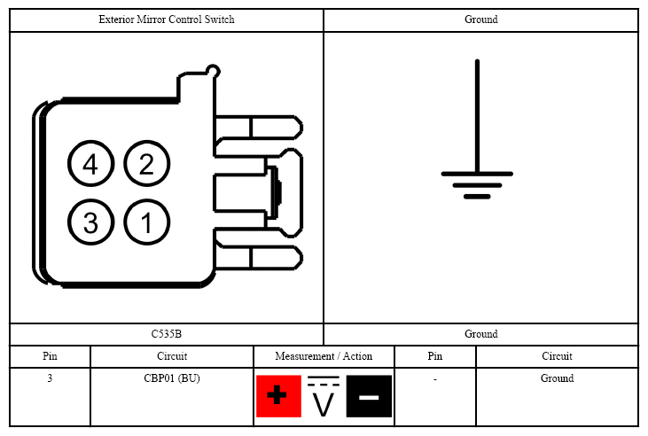
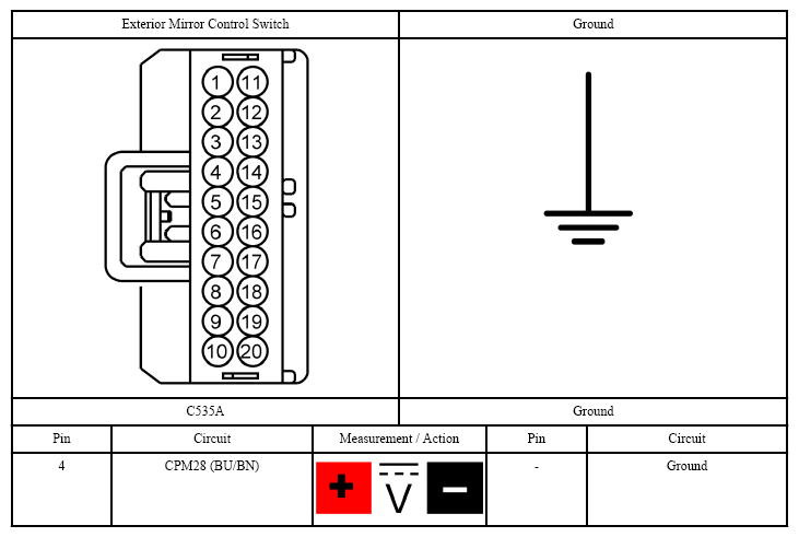
- CHECK FOR VOLTAGE TO THE EXTERIOR MIRROR CONTROL SWITCH
- Ignition OFF.
- Disconnect: Exterior Mirror Control Switch C535B (base mirrors).
- Disconnect: Exterior Mirror Control Switch C504 (heated mirrors).
- Ignition ON.
- For vehicles with base mirrors, measure:
 Courtesy of FORD MOTOR CO.
- For vehicles with heated mirrors, measure:
 Courtesy of FORD MOTOR CO.
- Is the voltage greater than 11 volts?
- Yes:
GO to step 2
.
- No:
VERIFY Body Control Module (BCM) fuse 48 (30A) (base mirrors) or 32 (15A) (heated mirrors) is OK. If OK, REPAIR the circuit. If not OK, REFER to the SYSTEM WIRING DIAGRAMS
to identify the possible causes of the circuit short.
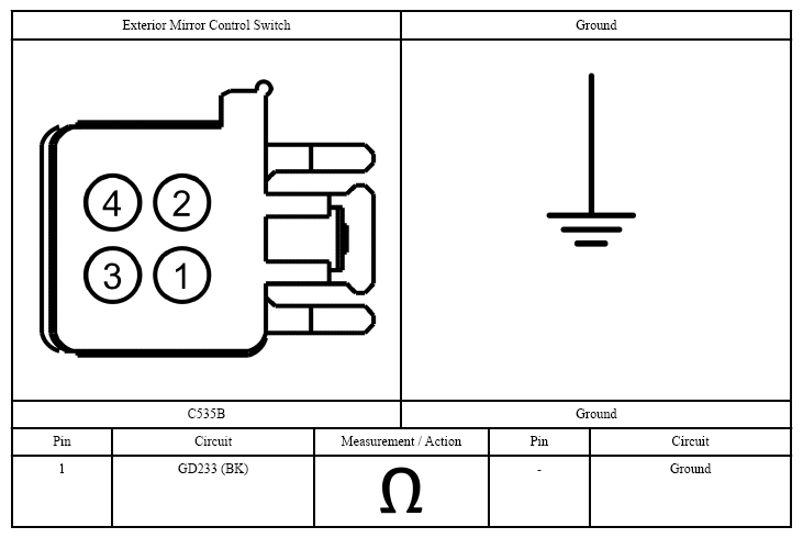
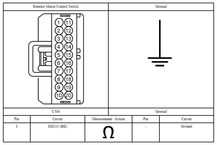
- CHECK THE EXTERIOR MIRROR CONTROL SWITCH GROUND CIRCUIT
- For vehicles with base mirrors, measure:
 Courtesy of FORD MOTOR CO.
- For vehicles with heated mirrors, measure:
 Courtesy of FORD MOTOR CO.
- Is the resistance less than 3 ohms?
- Yes:
GO to step 3
.
- No:
REPAIR the circuit.
- CHECK THE EXTERIOR MIRROR COMMON CIRCUIT FOR A SHORT TO VOLTAGE
- Disconnect: Left Hand (LH) Exterior Mirror.
- Disconnect: Right Hand (RH) Exterior Mirror.
- Disconnect: Exterior Mirror Control Switch C535A (base mirrors).
- Ignition ON.
- For vehicles with base mirrors, measure:
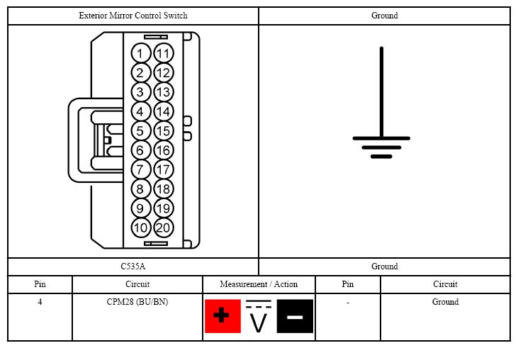 Courtesy of FORD MOTOR CO.
- For vehicles with heated mirrors, measure:
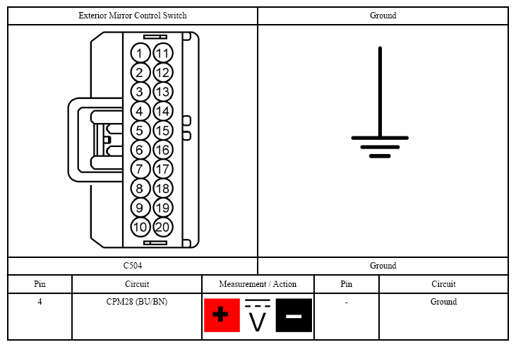 Courtesy of FORD MOTOR CO.
- Yes:
REPAIR the circuit.
- No:
GO to step 4
.
- CHECK THE EXTERIOR MIRROR COMMON CIRCUIT FOR A SHORT TO GROUND
- Ignition OFF.
- For vehicles with base mirrors, measure:
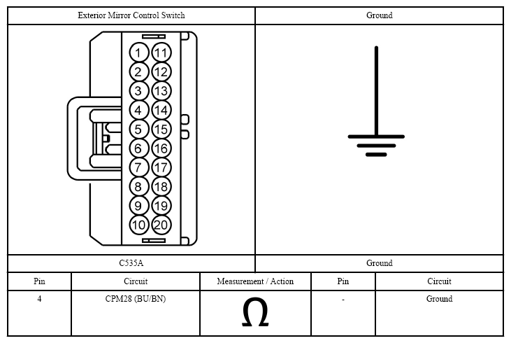 Courtesy of FORD MOTOR CO.
- For vehicles with heated mirrors, measure:
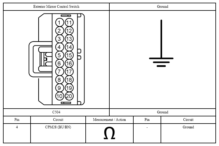 Courtesy of FORD MOTOR CO.
- Is the resistance greater than 10,000 ohms?
- Yes:
GO to step 5
.
- No:
REPAIR the circuit.
- CHECK THE EXTERIOR MIRROR COMMON CIRCUIT FOR AN OPEN
- For vehicles with base mirrors, measure:
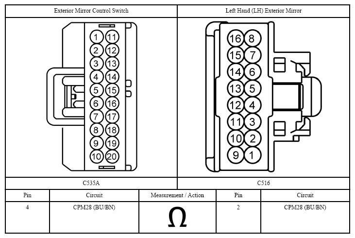 Courtesy of FORD MOTOR CO.
- For vehicles with heated mirrors, measure:
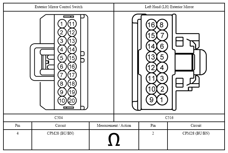 Courtesy of FORD MOTOR CO.
- Is the resistance less than 3 ohms?
- Yes:
INSTALL a new exterior mirror control switch (integral to the master window control switch). REFER to WINDOW CONTROL SWITCH
.
- No:
REPAIR the circuit.