Selector Lever Cable: Installation
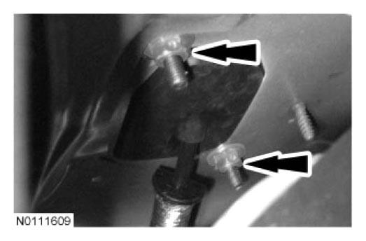
- Position the selector lever cable grommet in place.
- Install the 2 selector lever cable grommet nuts.
- Tighten to 9 Nm (80 lb-in).
 Courtesy of FORD MOTOR CO.
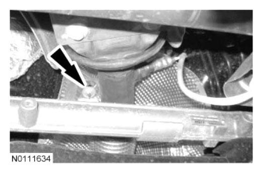
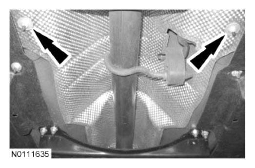
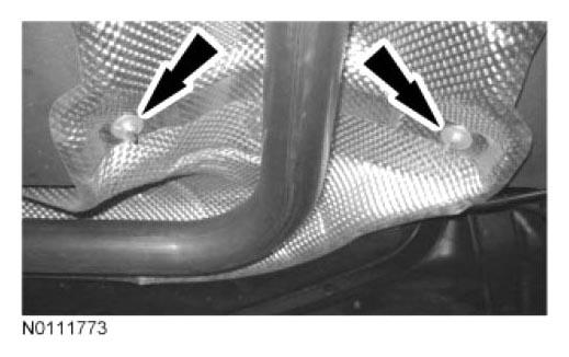
- Install the exhaust heat shield and the 6 exhaust heat shield fasteners (5 shown in illustration).
 Courtesy of FORD MOTOR CO.
 Courtesy of FORD MOTOR CO.
 Courtesy of FORD MOTOR CO.
- Install the cross brace and the 8 cross brace bolts.
- Tighten to 40 Nm (30 lb-ft).
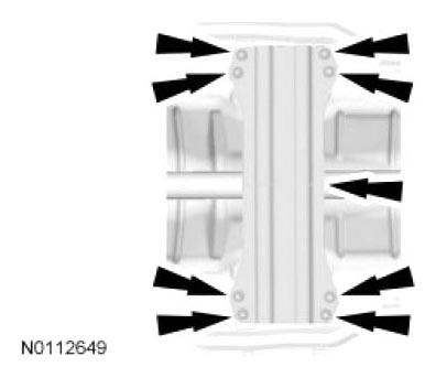 Courtesy of FORD MOTOR CO.
- Connect the exhaust hangers.
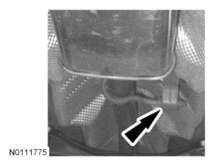 Courtesy of FORD MOTOR CO.
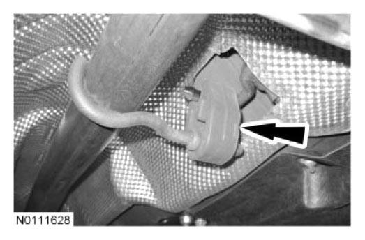 Courtesy of FORD MOTOR CO.
- Using a new exhaust flange gasket and 2 new exhaust flange nuts, connect the exhaust flange.
- Tighten to 47 Nm (35 lb-ft).
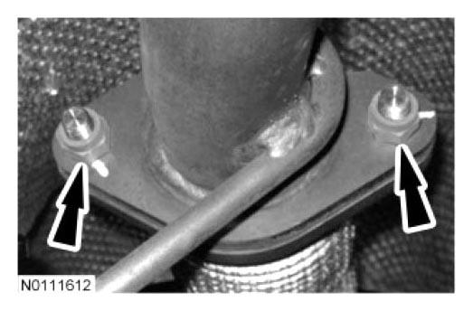 Courtesy of FORD MOTOR CO.
- Connect the selector lever cable to the selector lever cable bracket.
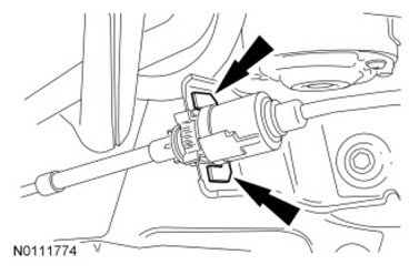 Courtesy of FORD MOTOR CO.
- Connect the selector lever cable end to the manual control lever.
 Courtesy of FORD MOTOR CO.
- Install the selector lever cable bracket bolt.
- Tighten to 10 Nm (89 lb-in).
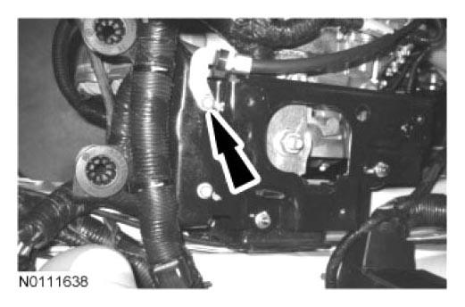 Courtesy of FORD MOTOR CO.
- Install the battery tray and the 3 bolts.
- Tighten to 10 Nm (89 lb-in).
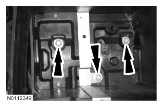 Courtesy of FORD MOTOR CO.
- Connect the 3 PCM electrical connectors.
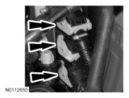 Courtesy of FORD MOTOR CO.
- Install the battery. For additional information, refer to
BATTERY, MOUNTING AND CABLES
.
- Install the selector lever cable on the selector lever housing.
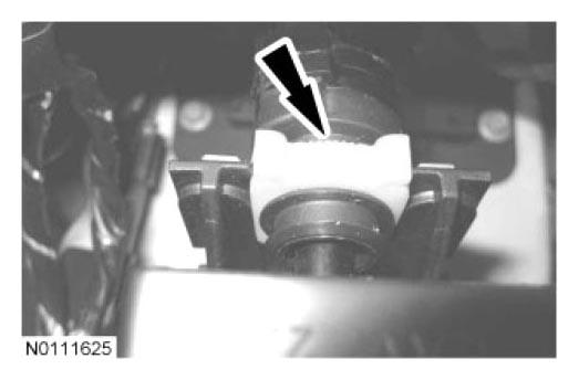 Courtesy of FORD MOTOR CO.
- Connect the selector lever cable end to the selector lever ball stud.
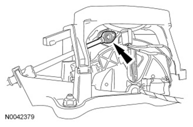 Courtesy of FORD MOTOR CO.
- Position the carpet back in place under the heater core and evaporator core housing.
- Install the floor console. For additional information, refer to
INSTRUMENT PANEL AND CONSOLE
.
- Adjust the selector lever cable. For additional information, refer to SELECTOR LEVER CABLE ADJUSTMENT in this information.