Throttle Switch (TS): M/T
- Remove air cleaner. Unplug throttle switch connector and loosen switch screws. Insert .024" (.60 mm) feeler gauge between throttle lever and stop screw. Connect DVOM between terminals "A" and "B" of switch. See Fig 1
.
- Turn switch fully counterclockwise, then slowly turn it clockwise until DVOM reads open (NO continuity). Hold and tighten switch screws to 18 INCH lbs. (2 N.m).
- Insert .035" (.90 mm) feeler gauge between throttle lever and stop screw. Ensure DVOM still reads NO continuity. Next insert .012" (.30 mm) feeler gauge and ensure continuity exists. Adjust throttle switch as necessary. Continue to check continuity with selected thickness gauges between throttle lever and stop screw. See THROTTLE SWITCH RESISTANCE table.
- If resistance value is incorrect at idle position only, adjust throttle switch and repeat test. If throttle switch cannot be adjusted to obtain the correct values, replace switch. Use THROTTLE SWITCH RESISTANCE table to test continuity of other terminals in same procedure. If all tests are okay, reconnect switch and install air cleaner.
THROTTLE SWITCH RESISTANCE (M/T ONLY)
| Application Condition |
Resistance (Ohms) |
| Between Terminals A-B |
Continuity |
| Between Terminals B-C |
No Continuity |
| Between Terminals A-C |
No Continuity |
| Between Terminals A-B |
No Continuity |
| Between Terminals B-C |
No Continuity |
| Between Terminals A-C |
No Continuity |
| Between Terminals A-B |
No Continuity |
| Between Terminals B-C |
Continuity |
| Between Terminals A-C |
No Continuity |
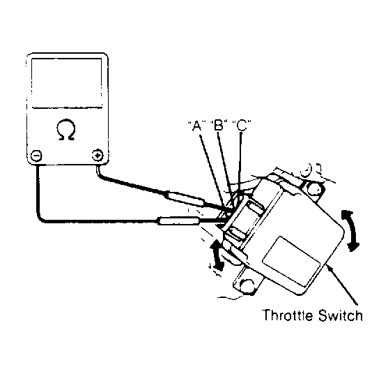 Courtesy of GENERAL MOTORS CORP.