System Testing
- Before proceeding with system test, check 25-amp rear defogger and 10-amp ignition fuses located in fuse/relay box. Fuse relay box is located near left kick panel. Ensure rear defogger grid is continuous and is NOT damaged. Ensure rear defogger indicator light ground is clean and tight. Rear defogger indicator light ground is located behind left kick panel. Ensure rear defogger ground, located on right side of tailgate, is clean and tight. Check rear defogger indicator bulb. Repair as required. If rear defogger still does not work properly, go to step 2).
- Turn ignition and rear defogger switches on. If defogger indicator light comes on and rear defogger starts to warm, go to step 3). If rear defogger indicator light comes on but rear window does not warm, go to step 4). If rear window warms but defogger indicator light does not light, go to step 9). If rear defogger indicator light does not light and rear window does not warm, go to step 10).
- Turn rear defogger switch off. If rear defogger indicator light goes out and rear window cools, system is working properly. If rear defogger indicator light remains on and rear window does not cool, go to step 13). If defogger indicator light goes out but rear window remains warm, go to step 14).
- Turn rear defogger switch on. Using a test light, backprobe terminal No. 1 (Black/Blue wire) of rear defogger connector C1. If test light glows, repair Black ground wire between rear defogger and ground connection. Ground connection is located on right side of tailgate, behind trim panel. See Fig 1
. If test light does not glow, go to step 5).
- Using a test light, backprobe rear defogger relay connector terminal No. 2 (Black/Blue wire). Rear defogger relay is located in fuse/relay box, near left kick panel. If test light glows, repair open in Black/Blue wire between rear defogger relay and rear defogger. If test light does not light, go to step 6).
- Remove rear defogger relay. Using a test light, backprobe rear defogger relay connector terminal No. 4 (Blue/Orange wire). If test light does not light, repair open in Blue/Orange wire between fuse/relay box and rear defogger relay. If test light glows, go to step 7).
- Connect test light to rear defogger relay connector terminal No. 1 (Orange/Yellow wire). If test light does not light, repair open in Orange/Yellow wire at rear defogger relay splice, between rear defogger switch and rear defogger indicator light. If test light glows, go to step 8).
- Check resistance using a digital ohmmeter. Connect ohmmeter leads between rear defogger relay connector terminal No. 3 (Black wire) and ground. Rear defogger relay is located in fuse/relay box, near left kick panel. If resistance is more than 3 ohms, repair Black ground wire between rear defogger relay and ground connection. Ground connection is located behind left kick panel. If resistance is less than 3 ohms, replace rear defogger relay.
- Disconnect instrument panel cluster 18-pin connector C4 connected to rear of fuse/relay box, near left kick panel. Connect a test light to terminal No. 1 (Orange/Yellow wire) of 18-pin connector C4. If test light does not light, repair open in Orange/Yellow wire splice between rear defogger switch and rear defogger indicator light. If test light glows, repair Black ground wire between 18-pin connector C4 and ground connection. Ground connection is located behind left kick panel.
- Connect instrument panel cluster 18-pin connector C4 if previously disconnected. Using a test light, backprobe terminal No. 1 (Orange/Yellow wire) of 18-pin connector C4. If test light glows, repair Black ground wire between 18-pin connector C4 and ground connection. Ground connection is located behind left kick panel. If test light does not light, go to step 11).
- Using a test light, backprobe rear defogger switch connector terminal No. 5 (Orange/Yellow wire). If test light glows, repair open in Orange/Yellow wire between rear defogger switch and rear defogger indicator light. If test light does not light, go to step 12).
- Using a test light, backprobe rear defogger switch connector terminal No. 2 (Blue/Red wire). If test light glows, replace rear defogger switch. If test light does not light, repair open in Blue/Red wire between fuse/relay box and rear defogger switch. Fuse/relay box is located near left kick panel.
- Disconnect rear defogger switch. If defogger indicator light goes out and rear window cools, replace rear defogger switch. If defogger indicator light remains on and rear window does not cool, repair short in Orange/Yellow wire between rear defogger switch, rear defogger relay and instrument panel cluster 18-pin connector C4. Defogger relay is located in fuse/relay box, near left kick panel. Instrument panel cluster 18-pin connector C4 is connected to fuse/relay box.
- Remove rear defogger relay. Rear defogger relay is located in fuse/relay box, near left kick panel. If rear window remains warm, repair short in Black/Blue wire between rear defogger relay and rear defogger. If rear window remains cool, replace rear defogger relay.
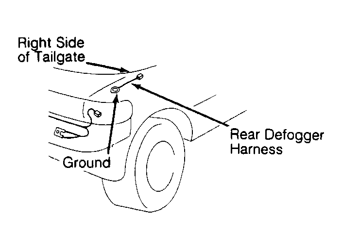 Courtesy of GENERAL MOTORS CORP.