Test No. 1
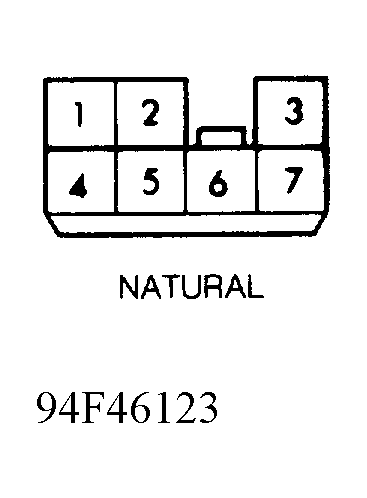
- Disconnect door lock control module connector located behind glove box inner panel. Connect positive lead of test light to connector terminal No. 1 (White/Black wire), and negative lead to ground. See Fig 1. Turn ignition on. If test light glows, go to next step. If test light does not glow, repair open in White/Black wire between fuse block and control module.
 Courtesy of GENERAL MOTORS CORP.
- Disconnect right door lock assembly connector. Using DVOM, measure resistance of Red wire between lock assembly connector terminal No. 1 and lock control module connector terminal No. 6. If resistance is less than one ohm, go to next step. If resistance is more than one ohm, repair open in Red wire.
- Disconnect instrument panel 13-pin connector. Using DVOM, measure resistance of Green/Yellow wire between IP connector terminal No. 4 and lock control module connector terminal No. 3. If resistance is less than one ohm, go to next step. If resistance is more than one ohm, repair open in Green/Yellow wire.
- Connect a test light between IP 13-pin connector terminal No. 10 (Black/Blue wire) and battery power. If test light glows, go to next step. If test light does not glow, check for poor ground connection at instrument panel support brace near cigarette lighter. If okay, repair open in Black/Blue wire.
- Reconnect IP 13-pin connector. Disconnect audio/alarm module connector, located under right side of instrument panel below radio. Raise and support vehicle drive wheels. Connect test light between battery power and audio/alarm connector terminal No. 6 (Black/Blue wire). Rotate left front wheel one revolution. If test light goes on and off 2 times, replace lock control module. If test light does not go on and off 2 times, check instrument panel printed circuit for cracks or damage. If okay, replace speedometer.