Testing (With Intermittent Wiper System)
- Turn ignition switch to ON position. Pull front wiper/washer switch back. If front washer pump operates and wipers complete at least one full sweep, go to next step. If front washer pump does not operate, go to step 6). If front washer pump operates and wipers do not complete at least one full sweep, go to step 17). If front washer pump continues to operate after front wiper/washer switch is released, go to step 21). If wipers continue to operate after front wiper/washer switch is released, go to step 22).
- Push front wiper/washer switch down to MIST position and release. If wipers operate for one sweep, go to next step. If wipers do not operate, replace combination switch. If wipers sweep more than once, replace combination switch.
- Turn front wiper/washer switch to INT position. If wipers sweep once every 6 seconds, go to next step. If wipers do not operate in intermittent mode, replace combination switch.
- Turn front wiper/washer switch to LO position. If wipers operate at low speed, go to next step. If wipers do not operate, replace combination switch. If wipers operate at high speed, go to step 10).
- Turn front wiper/washer switch to HI position. If wipers operate at high speed, system is operating properly. If wipers do not operate, go to step 12). If wipers operate in low speed, go to step 14).
- Using a test light, backprobe between combination switch Natural 20-pin connector terminal No. 17 (Yellow/Blue wire) and ground. See the COMBINATION SWITCH CONNECTOR TERMINAL ID
. See Fig 1
. If test light illuminates, go to next step. If test light does not illuminate, repair open in Yellow/Blue wire.
- Using a test light, backprobe between combination switch Natural 20-pin connector terminal No. 16 (Blue/Black wire) and ground. Hold washer switch in ON position. If test light illuminates, go to next step. If test light does not illuminate, check for open in Black wire combination switch and ground connection. If okay, replace combination switch.
- Turn ignition switch to LOCK position. Disconnect front washer pump and combination switch connectors. Using an ohmmeter, backprobe between combination switch Natural 20-pin connector terminal No. 16 (Blue/Black wire) and front washer pump connector terminal No. 2 (Blue/Black wire). If resistance is less than one ohm, go to next step. If resistance is one ohm or more, repair open in Blue/Black wire.
- Using ohmmeter, backprobe between front washer pump connector terminal No. 1 (Black wire) and ground. If resistance is less than one ohm, replace front washer pump. If resistance is one ohm or more, repair Black wire between front washer pump and ground connection.
- Using a test light, backprobe between front wiper motor connector terminal No. 1 (Blue/Red wire) and ground. If test light illuminates, go to next step. If test light does not illuminate, replace front wiper motor.
- Disconnect combination switch Natural 20-pin connector. Using a test light, backprobe between combination switch Natural 20-pin connector terminal No. 6 (Blue/Red wire) and ground. If test light illuminates, replace combination switch. If test light does not illuminate, repair short to battery voltage in Blue/Red wire.
- Using a test light, backprobe between front wiper motor connector terminal No. 1 (Blue/Red wire) and ground. Front wiper/washer switch should be in HI position. If test light does not illuminate, go to next step. If test light illuminates, replace front wiper motor.
- Using a test light, backprobe between combination switch Natural 20-pin connector terminal No. 6 (Blue/Red wire) and ground. If test light does not illuminate, replace combination switch. If test light illuminates, repair open in Blue/Red wire.
- Using a test light, backprobe between front wiper motor connector terminal No. 2 (Blue wire) and ground. Front wiper/washer switch should be in HI position. If test light does not illuminate, go to next step. If test light illuminates, replace combination switch.
- Using a voltmeter, backprobe between front wiper motor connector terminal No. 1 (Blue/Red wire) and ground. If voltage is less than 10 volts, go to next step. If voltage is 10 volts or more, replace front wiper motor.
- Disconnect front wiper motor and combination switch Natural 20-pin connectors. Using an ohmmeter, backprobe between combination switch Natural 20-pin connector terminal No. 6 (Blue/Red wire) and front wiper motor connector terminal No. 1 (Blue/Red wire). If resistance is less than 5 ohms, replace combination switch. If resistance is 5 ohms or more, repair Blue/Red wire.
- Using a test light, backprobe between front wiper motor connector terminal No. 2 (Blue wire) and ground. Pull back and hold front wiper/washer switch. If test light does not illuminate, go to next step. If test light illuminates, replace front wiper motor.
- Using a test light, backprobe between front wiper/washer switch connector terminal No. 5 (Blue wire) and ground. Pull back and hold front wiper/washer switch. If test light does not illuminate, go to next step. If test light illuminates, repair open in Blue wire.
- Using a test light, backprobe between front wiper motor connector terminal No. 4 (Yellow/Blue wire) and ground. If test light illuminates, go to next step. If test light does not illuminate, repair open in Yellow/Blue wire between front wiper motor and splice. See WIRING DIAGRAMS
.
- Disconnect combination switch Natural 20-pin connector. Move wipers out of park position. Using a test light, backprobe between front wiper motor connector terminal No. 3 (Blue/White wire) and ground. If test light does not illuminate, replace front wiper motor. If test light illuminates, check for an open in Blue/White wire. If wire is okay, replace combination switch.
- Disconnect combination switch Natural 20-pin connector. If front washer pump stops operating, replace combination switch. If front washer pump continues to operate, repair short to battery voltage in Blue/Black wire between front wiper/washer switch and front washer pump.
- Disconnect combination switch Natural 20-pin connector. If wipers continue to operate, go to next step. If wipers stop operating, replace combination switch.
- Disconnect front wiper motor connector. Using a test light, backprobe between front wiper motor connector terminal No. 2 (Blue wire) and ground. If test light illuminates, repair short to battery voltage in Blue wire. If test light does not illuminate, check for short to battery voltage in Blue/Red wire. If wire is okay, replace front wiper motor.
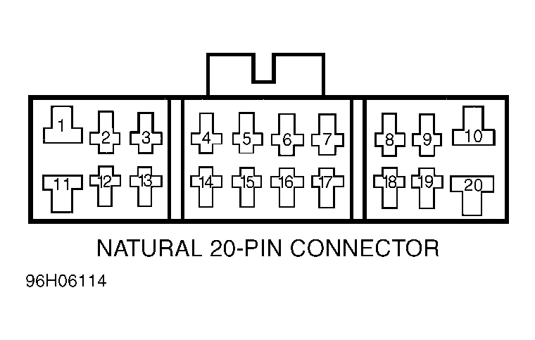 Courtesy of GENERAL MOTORS CORP.
 COMBINATION SWITCH CONNECTOR TERMINAL ID
| Terminal No. (Wire Color) |
Circuit |
| 1 (RED) |
Dimmer Switch (High Beam) |
| 2 (GRN/RED) |
Left Turn Signal Switch |
| 3 (YEL/WHT) |
Turn Signal/Hazard Switch |
| 4 (BLU/GRN) |
Horn/Brush Slip Ring |
| 5 (BLU) |
Wiper/Washer Switch (Low Speed) |
| 6 (BLU/RED) |
Wiper/Washer Switch (High Speed) |
| 7 (BLU/WHT) |
Wiper/Washer Switch (Park Position) |
| 8 (RED/YEL) |
Parking Light Switch |
| 9 (BRN/YEL) |
DRL Control Module (If Equipped) |
| 10 (WHT) |
TAIL/DOME (15-Amp) Fuse |
| 11 (RED/WHT) |
Dimmer Switch (Low Beam) |
| 12 (GRN/YEL) |
Right Turn Signal Switch |
| 13 (GRN) |
Turn Signal & Hazard Switch |
| 16 (BLU/BLK) |
Wiper/Washer Switch (Wash) |
| 17 (YEL/BLU) |
WIPER/WASHER (15-Amp) Fuse |
| 18 (WHT/GRN) |
HAZ (15-Amp) Fuse |
| 19 (YEL) |
TURN BACK (15-Amp) Fuse |
| 20 (BLK) |
Light Switch Ground |